In this section, we will delve into some theoretical foundations of alternating current (AC) circuit switching and various designs of electrical circuits and components used in this realm of electronics. A separate section in this chapter will be dedicated to practical work on switching AC circuits.
What is Alternating Current (AC)?
Unlike
direct current (DC), which flows consistently in one direction,
alternating current (AC) doesn't maintain such consistency. In some countries (including the United States), the direction of AC current changes 120 times per second, and in the rest of the world, it changes 100 times per second. Such reversals in current direction correspond to voltage changes across the load (as shown below). Each complete cycle consists of two alternating current directions, so the frequency of AC is either 60 or 50 Hz (cycles per second). Hertz is the unit of frequency, and 1 Hz equals one cycle per second.
In the United States and some other countries, the voltage in the AC power grid is 120 V, while in most of the rest of the world, AC power outlets feature a much more life-threatening voltage of 220-230 V.

-
image.png (52.38 KiB)
AC voltage Viewed 19309 times
As shown in Fig., the peak positive and negative phases of the voltage are actually significantly higher than 120 V. This is because the value of 120 V AC is effectively an averaged value representing the equivalent of direct current voltage capable of supplying the same amount of power to the load. Therefore, direct current at 120 V will make an old-fashioned incandescent lamp glow with the same brightness as when powered by 120 V AC.
Relays
You have already worked with relays when studying the section "Controlling a DC Motor with Relays." In that context, relays were used to switch a direct current motor. The relay coil is isolated from the part where the switching contacts are located, which plays a crucial role in the safety of switching AC circuits. Most relay devices have their switching capabilities specified on their housings. For example, a typical "sugar cube" relay might be labeled with its ability to switch 10 A of AC current at 250 V and 10 A of DC current at 24 V.
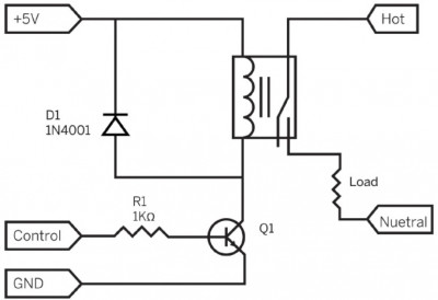
The image below illustrates how a relay can be used to switch an AC load. It's important to remember that to control the relay coil from an Arduino or Raspberry Pi digital output, you need a current that significantly exceeds what the output can provide. Therefore, a small transistor Q1 is included in the relay control circuit.

-
image.png (47.59 KiB)
AC switching with relays Viewed 19309 times
Control signal lines, 5 V, and ground are connected to Arduino or Raspberry Pi boards. When a high voltage level is applied to the control line, transistor Q1 turns on, powering the relay coil. The relay coil then closes its contacts, connecting the AC phase wire to one end of the load (the switching device). The other end of the load is connected to the AC neutral wire.
Optocouplers
Replacing rapidly outdated relays in many alternating current (AC) circuit switching designs are solid-state relays (SSRs), which will be discussed further in the "Solid-State Relays (SSR)" section. One of the key components of solid-state relays is the optocoupler - a component based on transistor technology, with the primary purpose of isolating the low-voltage control circuit used in the project from the hazardous high-voltage AC load circuit.

-
image.png (37.09 KiB)
Optron Viewed 19309 times
An optocoupler combines a light-emitting diode (LED) and a photosensitive element (typically a phototransistor) in a single plastic package.
The crucial aspect of the optocoupler's design is the absence of electrical connection between the LED and the phototransistor. Their connection is entirely optical: the conducting path of the phototransistor opens when the LED emits light. The phototransistor is a low-power device, and before controlling any AC device, it requires additional electronic circuitry.
Optocouplers are sensitive devices, and their LED circuit can be directly controlled from an Arduino output and even from a Raspberry Pi general-purpose input/output (GPIO) pin - when using an isolating resistor of 1 kΩ to limit the current to a few milliamperes.
Optocouplers and Zero-Crossing Solid-State Relays
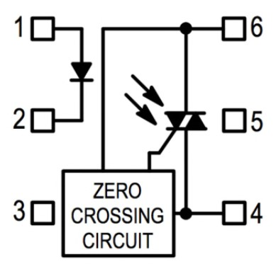
Optocouplers designed for AC circuit switching have specific features. First, on their photosensitive side, they use not a regular bipolar phototransistor but a device called a
phototriac (short for TRIode for AC), designed to work in AC circuits. The internal structure of a phototriac (e.g., type MOC3031) is shown in the figure below, and its datasheet in PDF format can be downloaded from
http://www.farnell.com/datasheets/1639837.pdf.

-
image.png (72.05 KiB)
Optocoupler with zero crossing circuitry Viewed 19309 times
A triac is a specialized type of transistor designed for switching current in both directions, which is essential for controlling AC circuits.
Another characteristic of a triac is that, once the circuit is opened, it remains in the open state. It will stay in this state until the current passing through it is practically reduced to zero. This makes it entirely unsuitable for controlling direct current devices. However, since AC changes polarity 120 times per second, the triac can switch off as many as 120 times per second.
The advantage of the triac staying open is that it closes only when the current (and consequently, the voltage across it) falls, reducing the commutation current that would otherwise have very high values. This current commutation at its minimal values also reduces electrical noise. The "softness" of the commutation is further enhanced by using the zero-crossing circuit, incorporated into some optocouplers. This circuit delays the triac's activation until the voltage passes through zero, guaranteeing soft both turn-off and turn-on.
The triac built into an optocoupler like the MOC3031 is a low-power device and is solely intended for use in control circuits of a more powerful triac, which handles the actual switching of AC circuits.
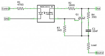
A typical electrical circuit for using an optocoupler with zero-crossing switching to control a high-power triac is shown in the diagram below.

-
image.png (51.46 KiB)
Switching AC circuits using an optocoupler with zero crossing switching circuitry Viewed 19309 times
Controlling a high load with Arduino or Raspberry Pi in such circuits becomes a matter of delivering just one or two milliamperes to the LED inside the optocoupler.
Resistors R2 and R3 limit the current flowing through the low-power phototriac in the optocoupler, and resistor R4 and capacitor C1 are intended for "smoothing" any voltage spikes that may occur in the circuit, despite the soft switching.