Page 1 of 1

Displays

Posted: 13 Oct 2023, 06:40
by Oleg
Not only can you connect a monitor to the Raspberry Pi, but there are also a multitude of different output devices capable of displaying text, numbers, or graphics, and you can even control entire LED panels. To cover each type of existing display in detail would take too much time, so in this chapter, we'll focus on the most practical and interesting displays and some complementary devices.

Addressable LEDs

Posted: 13 Oct 2023, 06:42
by Oleg
RGB LEDs consist of three light-emitting diodes combined in a single housing. Another type of LEDs, known as "addressable LEDs," also include a control microchip within their housing. This microchip controls the intensity of the three LED colors using pulse-width modulation (PWM), similar to how it's done with Arduino or Raspberry Pi. It's worth noting that the control microchip is integrated directly into the LED itself.

Addressable LEDs are designed for controlling a large number of them using a single microcontroller or computer, such as Arduino or Raspberry Pi. You can purchase addressable LEDs at Adafruit, which they call NeoPixels (note that the name NeoPixels is used quite frequently, especially on websites and descriptions of other addressable LEDs unrelated to Adafruit). The most popular of these are WS2812 type addressable LEDs. They support a standard serial data transmission, allowing you to create long chains of these LEDs to build large displays. In addition to using them as RGB addressable LEDs, WS2812 LEDs can also be used as single-color light emitters.

Sometimes, addressable LEDs are arranged in a matrix form, but you can also purchase them as a roll of tape from which you can cut LED strips of the desired length for your project (see the image below).
image.png
image.png (95.96 KiB)
Viewed 3427 times
In Figure 14.1, you can see that the tape is divided into segments, resembling a ribbon or a roll of film. Three wires on each side of the LED carry ground (GND) and 5V power supply (5V) as well as serial data D0, which is transmitted from one LED to another throughout the strand. In other words, one LED's output is connected to the input of the next. A vertical bar is drawn in the middle of the segments, indicating the spot to cut the LED strip if you need to shorten it.

Pay attention to the arrows on the tape, indicating the direction of the serial data flow. According to this direction, when connecting LEDs, you should always attach to the left side of the strip.

Experiment: Controlling a Display with RGB LED Strips

Posted: 13 Oct 2023, 06:54
by Oleg
When acquiring one or two meters of LED strip, you'll likely want to try it out in practice. Connecting it to an Arduino is quite straightforward (see the diagram), but connecting the strip to a Raspberry Pi will require some additional effort.
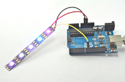
LED strip connected to Arduino
image.png (154.37 KiB)
LED strip connected to Arduino Viewed 3427 times
Components

To conduct this experiment with Arduino, you will need the following components:
1. WS2812 Addressable LED strip
2. Three "male-to-male" jumper wires

Since the logic input of NeoPixels LEDs is not compatible with 3V logic signals, additional components are needed for the Raspberry Pi experiment. However, before taking additional steps, it's worth trying to work without a level shifter, as your LED strip may function properly with 3V logic signals.

Nevertheless, for the Raspberry Pi experiment, you may need the following additional components:
1. 400-point breadboard
2. R1, R2: Two 470 Ohm 0.25W resistors
3. Q1: MOSFET transistor 27000
4. 01: "female-to-male" jumper wires

Note that for this experiment, a low-power MOSFET transistor 27000 is used, as it handles high-frequency serial data better compared to 2N3904. You can also use a transistor like FQP30N06L, but its power handling capability would be excessive for this experiment.

Arduino Connection

On one end of the LED strip, there's usually a cable with a three-pin connector, attached to GND, 5V, and D0. If this connector is present, you can use "male-to-female" jumper wires to connect it to a breadboard or Arduino. If there's no connector, you can carefully solder wires to the GND, 5V, and D0 pins on the left edge of the strip.

I used three "male-to-male" jumper wires, cutting off one side of the connectors and soldering them to five NeoPixel LEDs on the strip. Then, these three connectors can be directly connected to the Arduino, as shown in the diagram, with the D0 contact of the LED strip connected to pin 19 on the Arduino.
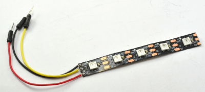
User-friendly NeoPixel display
image.png (109.45 KiB)
User-friendly NeoPixel display Viewed 3427 times
Power Consumption of Addressable LEDs

When increasing the brightness of NeoPixel LEDs to their maximum power, they consume a significant current (approximately 60 mA per LED). If you have five NeoPixel LEDs connected, this can lead to a total consumption of 300 mA, which might be too high a load for Arduino or Raspberry Pi. In such a case, you may need to connect an external 5V power source to the LED strip.

Arduino Program

The folks at Adafruit have developed a library for Arduino that greatly simplifies the management of long chains of addressable LEDs. You can download this library from the following link: [https://github.com/adafruit/Adafruit_NeoPixel](https://github.com/adafruit/Adafruit_NeoPixel) and install it in your Arduino environment.

To conduct the experiment with Arduino, you'll need to use a sketch.

Code: Select all

#include <Adafruit_NeoPixel.h>  // 1

const int pixelPin = 9;    // 2
const int numPixels = 5;   // 3

Adafruit_NeoPixel pixels = Adafruit_NeoPixel(numPixels, pixelPin, NEO_GRB + NEO_KHZ800); // 4

void setup() {
  pixels.begin(); // 5
}

void loop() {
  for (int i = 0; i < numPixels; i++) { // 6
    int red = random(255);
    int green = random(255);
    int blue = random(255);
    pixels.setPixelColor(i, pixels.Color(red, green, blue)); // 7
    pixels.show(); // 8
  }
  delay(100L); 
}

[()][/] Let's take a closer look at this sketch, breaking it down into the points described in the comments:

1. Import the Adafruit NeoPixel library.
2. If you need to use a different pin to control the NeoPixel LEDs, edit this part of the code.
3. If you have more or fewer LEDs in your NeoPixel chain, make changes here. Note that you should consider power consumption, as described earlier.
4. Initialize the NeoPixel library according to your settings.
5. Start sending data to the display.
6. Set a random color for each pixel, update the display, and add a 1/10-second delay before changing the color of all the LEDs. Now it's time to disco dance!
7. The setPixelColor function takes two parameters: the index of the pixel to set and the color, represented by three values ranging from 0 to 255 for each of the three color channels.

Project: Adding a Display to the Beverage Cooler Project

Posted: 26 Jul 2024, 05:16
by robotwf
To understand how an OLED display works in conjunction with Arduino, let's take the material from the section "Project: Thermostatic Beverage Cooler" as a basis and replace the green LED, which is used to indicate the cooling mode of the cooler, with an OLED display. This display will show both the current and set temperatures (see the diagram below).
Image

Components

For this project, in addition to the components used in the section "Project: Thermostatic Beverage Cooler" (excluding the green LED and resistor R3), you will need an OLED display similar to the one used in the section "Experiment: Using I²C display with Raspberry Pi", as well as four male-to-female jumper wires.

Connecting to Arduino

If you have not done so already, assemble the circuit described in the section "Project: Thermostatic Beverage Cooler" In this project, you do not need to add the green LED and resistor R3.

You can connect the OLED display directly to the Arduino, avoiding the use of a breadboard and reducing interference. The diagram below shows only the new part of the project with the OLED display connected to the Arduino. When connecting the wires to the pins of the OLED module, be careful not to confuse the 5V and GND pins.
Image

Arduino program

As expected, there is an Arduino library available for working with OLED displays (https://github.com/adafruit/Adafruit_SSD1306). Therefore, you need to download and install this library in your Arduino development environment.

For this version of the cooler, the program is nearly the same as the one without the display. The changes include adding the following libraries: `Adafruit_GFX.h` and `Adafruit_SSD1306.h`.

Code: Select all

#include <OneWire.h>
#include <DallasTemperature.h>
#include <PID_v1.h>
#include <SPI.h>
#include <Wire.h>
#include <Adafruit_GFX.h>
#include <Adafruit_SSD1306.h>

const double minTemp = 0.0;  
const double maxTemp = 20.0;

double kp = 1500;     
double ki = 50.0;
double kd = 0.0;

const int tempPin = 2;
const int coolPin = 9;    
const int potPin = A0;
const long period = 1000; // >750

OneWire oneWire(tempPin);
DallasTemperature sensors(&oneWire);
Adafruit_SSD1306 display(4);

double setTemp = 0.0;
double measuredTemp = 0.0;
double outputPower = 0.0;     
long lastSampleTime = 0;

PID myPID(&measuredTemp, &outputPower, &setTemp, kp, ki, kd, REVERSE); 

void setup() {
  pinMode(coolPin, OUTPUT);
  Serial.begin(9600);
  sensors.begin();
  myPID.SetSampleTime(1000); // (4)
  myPID.SetMode(AUTOMATIC);  
  display.begin(SSD1306_SWITCHCAPVCC, 0x3c);
}

void loop() { 
  long now = millis();         
  if (now > lastSampleTime + period) {
      checkTemperature();
      lastSampleTime = now;
  }
  setTemp = readSetTempFromPot(); 
}

void checkTemperature() {      
  measuredTemp = readTemp();  
  Serial.print(measuredTemp);
  Serial.print(", ");
  Serial.print(setTemp);
  Serial.print(", ");
  Serial.println(outputPower);
  myPID.Compute();
  analogWrite(coolPin, outputPower);
  updateDisplay();
}

double readSetTempFromPot() {   
  static double oldTemp = 0;
  int raw = analogRead(potPin);
  double temp = map(raw, 0, 1023, minTemp, maxTemp);
  if (oldTemp != temp) {
    updateDisplay();
    oldTemp = temp;
  }
  return temp;
} 

double readTemp() {
  sensors.requestTemperatures(); 
  return sensors.getTempCByIndex(0);  
}

void updateDisplay() {
  display.clearDisplay();
  display.setTextSize(2);
  display.setTextColor(WHITE);
  display.setCursor(0,0);
  display.print("Temp:");
  display.println(measuredTemp);
  display.print("Set: ");
  display.println(setTemp);
  display.display();
}
  
The variable `display` is defined to access the library. The parameter `4` is the actual pin number used for connecting to the Enable pin of the display (if it exists). In our displays, there is no Enable pin, so the number 4 is not used for anything else in Arduino.

Adafruit_SSD1306 display(4);

The `setup()` function includes the following line, which initializes the display:

display.begin(SSD1306_SWITCHCAPVCC, 0x3C);

The `loop()` function now calls a new function `updateDisplay()` to update the display content with the current temperature every second:

void loop() {
updateDisplay();
// Other operations of your program
}


The `updateDisplay()` function clears the screen, sets the text size and color, and then displays the current and set temperatures on the screen:

Code: Select all

void updateDisplay() {
  display.clearDisplay();
  display.setTextSize(2);
  display.setTextColor(WHITE);
  display.setCursor(0, 0);
  display.print("Температура:");
  display.println(measuredTemp);
  display.print("Установка: ");
  display.println(setTemp);
  display.display();
}
The `readSetTempFromPot()` function has been slightly modified to update the set temperature immediately upon change, without waiting for the next second:

double readSetTempFromPot() {
static double oldTemp = 0;
int raw = analogRead(potPin);
double temp = map(raw, 0, 1023, minTemp, maxTemp);
if (oldTemp != temp) {
updateDisplay();
oldTemp = temp;
}
return temp;
}


The keyword `static` before the definition `oldTemp` means that the variable will retain its value between calls to the `readSetTempFromPot()` function. Both variables, `temp` and `oldTemp`, are of type `double` (double-precision floating-point number) as this type is used in the DS18B20 library.

Now you have a program that allows you to use an OLED display in the beverage cooler project. If needed, you can enhance it with additional functions or improve the interface for displaying information on the display. Back to the beginning