So, now you know how to turn an LED indicator on and off. Armed with this knowledge, let's try to start and stop an electric motor. To do this, we will use the same programs as described earlier in the "Experiment: LED Control" section, but for controlling the motor, we will use a switch.
We'll delve deeper into DC motors later. For now, it's sufficient to know that in this experiment, we are using small motors similar to those found in handheld fans or toy cars. These motors are the easiest to use: they start spinning when voltage is applied across their two terminals. Since most motors require a current stronger than what the digital outputs of a Raspberry Pi or Arduino can provide, we can't power the motors directly from them. Instead, we'll include a transistor in the circuit, allowing the weak current from Raspberry Pi or Arduino to control a much stronger current powering the electric motor.
Whether you are working with Raspberry Pi or Arduino, the same electronic components are used in both cases and are mounted on identical breadboards.
Keep in mind that there will be more components on the breadboards than in the first experiment, so ensure that all their pins are inserted into the correct holes, and make sure that the components themselves are functioning correctly and properly installed.
Components
For this experiment, you will need the following components:
- Composite transistor (Darlington pair) MPSA14
- Small direct current (DC) motor with a 6V power supply (Battery compartment: 4 AA batteries - 6V)
- Male-Female jumper wires (for Raspberry Pi only)
Remember that Male-Female jumper wires are only needed if you plan to perform this experiment with a Raspberry Pi.
Breadboard Layout
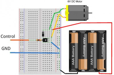
The breadboard layout for this project is shown in the diagram. After placing all the components on the breadboard, make sure that the transistor is oriented correctly, with its flat side facing to the right. Also, verify the orientation of the diode; it has a stripe on one side, and this side should be pointing towards the upper part of the board.

-
image.png (132.22 KiB)
Layout of the layout board for engine control Viewed 25214 times
Experiments Without Arduino or Raspberry Pi
Before connecting the breadboard to Arduino or Raspberry Pi, you can test and experiment with it without such connections. In this setup, the transistor acts as a switch. Consequently, two wires will be connected to the board (Arduino or Raspberry Pi): a control wire and a ground wire.
Ground (GND) corresponds to zero volts, both for the breadboard and for the Arduino or Raspberry Pi boards. The
control connection starts the motor when connected to any power source with a voltage greater than 2V. When the voltage drops below this level, the motor will turn off.
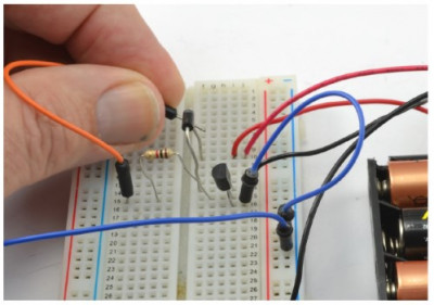
Practice using a Male-Male jumper wire before moving on to using Arduino or Raspberry Pi. Insert one end of the wire into the same row as the left output of the resistor, and connect the other end to the upper contact of the diode, which is connected to the positive terminal of the battery. The motor will start running, but as soon as you remove the jumper wire from the diode's pin, the motor will stop.

-
image.png (228.54 KiB)
Checking the circuit before connecting an Arduino or Raspberry Pi to it Viewed 25214 times
Connecting to Arduino
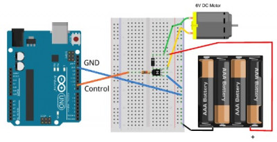
Now that you've verified that the control output from the breadboard indeed starts and stops the motor, you can connect it to one of the GPIO (General Purpose Input/Output) pins on the Arduino using a Male-Male jumper wire. Use pin
9 for this purpose. Note that we've worked with this control pin before (see the "Experiment: LED Control" section).
Additionally, you'll need to connect another wire - the ground wire (
GND) - to the
GND pin on the Arduino board. This is also shown in the diagram.

-
image.png (118.22 KiB)
Layout of the breadboard for motor control using Arduino Viewed 25214 times
Experimenting with Arduino
If your Arduino board still has the program from the previously discussed "Experiment: LED Control" section loaded onto it, there's no need to upload anything new. If that program is no longer on the Arduino, refer back to that section to upload it again.
Just like in the LED experiment, you can play with the numbers in the delay functions to change the motor's operation duration in each cycle.