Resistors
Resistors may appear as small components with colorful bands on them. To determine the resistance value of a resistor, you can measure it with a multimeter or decipher it based on the color bands. Each color corresponds to a number:
Black - 0
Brown - 1
Red - 2
Orange - 3
Yellow - 4
Green - 5
Blue - 6
Violet - 7
Gray - 8
White - 9
Gold - 1/10
Silver - 1/100
 NOTE
NOTE
The gold and silver colors not only indicate fractions, 1/10 and 1/100, respectively, but also represent the precision of the resistor. Gold means ±5%, while silver means ±10%.
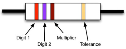
Typically, resistors have three such color bands at one end, followed by a gap and another band at the other end, which denotes the accuracy of the resistor's value.
The arrangement of the colored bands is shown in the diagram. The value of the resistor is determined by the first three bands: the first corresponds to the first digit, the second to the second digit, and the third is the "multiplier," indicating how many zeros to add after the first two digits.
Based on what was mentioned, the resistor depicted in the diagram has a resistance of 270 ohms: the first digit is 2 (red band), the second is 7 (violet band), and the multiplier is 1 (brown band), adding two zeros after the digits 27. Similarly, a 1 kohm resistor will have brown, black, and red bands (1, 0, 00).
Resistors also vary in nominal power ratings. Almost all common resistors of the type used in the circuits of this book (for through-hole mounting) have a power rating of 0.25 watts. Other common nominal power values include 0.5 watts, 1 watt, and 2 watts, with higher-rated resistors being physically larger.
Transistors
Typically, any electronics component supplier offers an immense variety of
transistors. To simplify the search, I have selected only four transistors for use in this book. These transistors form the basis for creating nearly all electronic circuits capable of controlling various devices connected to Arduino and Raspberry Pi.
The transistor mentioned in the "Experiment: Motor Control" section is precisely the component that allows weak current, such as a few milliamperes, to control hundreds of milliamperes supplied to a motor. While transistors can be used for other purposes, in this book, they will serve as switches. A small current flows into the transistor's base and then to the ground (GND) through the transistor's
emitter. This current will switch a much stronger current from the
collector to the
emitter. The image below shows an assortment of transistors of different types that can handle various power levels.
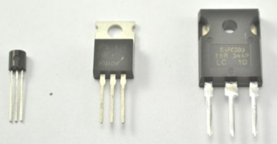
There are only a few different transistor package styles. It is impossible to determine their properties solely by their appearance; you need to read what is written on them.
The most common package variants are TO-92 (left in the image) and TO-220 (center in the image). Occasionally, for handling very high currents, transistors with larger packages, like TO-247 shown on the right in the image, may be used. Models TO-220 and TO-247 are intended for mounting on heat sinks. However, if you are using these transistors at currents significantly lower than their maximum ratings, it is not necessary to mount them on heat sinks.
Bipolar Transistors
Transistors are manufactured using various technologies, each with its own advantages and disadvantages. Therefore, a transistor that suits one situation may not be suitable for another.
When starting to work with transistors, you will most likely encounter
bipolar transistors. They have remained largely unchanged since the early days of the transistor industry. The advantage of such transistors is their affordability and ease of use at low load currents. However, they also have a drawback. Although a small current flowing from the base to the emitter of the transistor can allow a stronger current to flow from the collector to the emitter, the collector current is limited by the base current multiplier (called the
current gain or
hFE), which usually ranges from 50 to 200. Therefore, if the Raspberry Pi provides a base current of 2 mA, the collector current cannot exceed 100 mA. This current is much lower than what you might expect, as the transistor can handle a higher current (e.g., 500 mA). Still, it will never reach that limit because the base current is simply not sufficient. When working with Arduino, this problem usually does not arise because Arduino allows a higher base current (up to 40 mA) if you use a weaker resistor instead of a 1 kohm resistor. For example, if you use a 150 ohm resistor, the base current increases to:
1-V/R=(5-0.5)/150=30 mA.
Even in the worst-case scenario, if the transistor has a current gain of 50, a base current of 30 mA will result in a collector current of 1.5 A.
It should be noted: in the example just discussed, the voltage is calculated as (5 - 0.5) because the voltage between the base and emitter of the bipolar transistor, when the transistor is on, is about 0.5 V.
In this book, we will work with only one model of bipolar transistor, the widely used 2N3904. Although there are bipolar transistors that can handle higher currents, it is better to use more advanced transistors when dealing with higher current loads.
Composite Transistors
When you need greater amplification, for instance, if you're controlling a small motor with a Raspberry Pi board that can only provide a few milliamperes to the base, it's convenient to use a
composite transistor (often referred to as a
Darlington pair) instead of a regular bipolar transistor. Composite transistors typically have a gain factor of no less than 10,000.
A composite transistor contains two bipolar transistors in a single package (as shown in the diagram below), and it's this two-component structure that gives composite transistors their high gain factor.
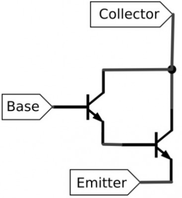
Because a composite transistor has two components, each with its own base and emitter, when the transistor is on, each pair produces a voltage drop of at least 0.5 V. This results in a total voltage drop of 1 V, rather than the 0.5 V you'd have with a typical bipolar transistor. In reality, this voltage drop also affects the collector voltage and increases with higher load currents. Therefore, when we control a current of 1 A, the composite transistor MPSA14 is practically capable of providing us only 9 V, even though the load voltage is 12 V. In some cases, this matters; in others, it doesn't.
The transistor in the "Experiment: Motor Control" section is a composite transistor MPSA14. When using a Raspberry Pi, the voltage drop across resistor R1 will not be 3.3 V but 3.3 V + 1 V = 2.2 V. Accordingly, Raspberry Pi will need to provide a current of 2.2 V / 1 kohm = 2.2 mA.
In addition to the low-power transistor MPSA14, which is convenient for controlling loads up to 0.5 V, I also recommend working with a more powerful composite transistor, the TIP120, which is a standard component and should definitely be in your parts box.
MOSFET Transistors
In principle, a bipolar transistor is a current-controlled device: a small base current is amplified and turned into a large collector current. However, there is another type of transistor called a
field-effect transistor, or
MOSFET transistor (short for "metal-oxide-semiconductor field-effect transistor"), which requires a very small current to switch but remains in the on state as long as the voltage on its input gate exceeds a certain threshold value.
The diagram below schematically represents such a transistor. As you might guess, the input component of this transistor (the gate) is not electrically connected to the other transistor components.
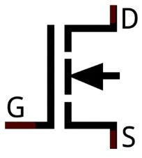
Note: Unlike a bipolar transistor, whose components are called the base, collector, and emitter, the components of a MOSFET transistor are called the gate (
G), drain (
D), and source (
S). You might think that the source is equivalent to the collector, but in reality, the collector of a bipolar transistor is equivalent to the drain of a field-effect transistor.
When working with Arduino or Raspberry Pi, it is highly advisable to use MOSFET transistors to switch devices in the circuit, as this can be done with minimal current. You just need to ensure that the voltage at the transistor's gate is above its threshold value. The gate threshold voltage is the point at which the MOSFET transistor turns on and allows current to flow from the drain to the source. The diagram shows how to connect a MOSFET transistor for controlling a load. As you can see, the connection is essentially the same as with a bipolar transistor.
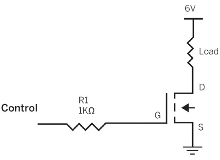
In the circuit shown in the diagram, two symbols are used that we have not encountered before. From the source of the transistor (
S), there is a line with three parallel lines that gradually shorten. This is a ground symbol - using it in the circuit eliminates the need for additional connecting lines.
The second symbol is located at the top of the circuit and is just a horizontal line marked with
6 V. It signifies that the voltage in this part of the circuit will be 6 V, eliminating the need to draw a battery.
Transistor Pinout May Vary
While we try to use transistors with compatible pinouts (lead arrangements), this rule is not universal. Not all transistors in similar packages have the same pinout, so always check the datasheet before using a new transistor.
After reviewing the diagram above, you might wonder why we still need resistor R1, considering that no current is drawn by the gate. The reason is that having this resistor is still prudent because increasing the voltage at the gate for even a fraction of a second can result in a sudden surge of current. The resistor ensures that such a surge won't damage the GPIO contact.
The complexity of working with MOSFET transistors lies in the fact that sometimes their gate threshold voltage is too high to be switched by a 3.3 V signal from a Raspberry Pi or a 5 V signal from an Arduino. MOSFET transistors with gate threshold voltages low enough to be switched directly from the GPIO contacts of our boards are known as
logic-level MOSFETs. For this book, two standard MOSFET transistors are chosen: the 2N7000 for low-power applications and the FQP30N06L for relatively high-power applications. Both have a guaranteed gate threshold voltage of no more than 3 V, making them suitable for use with both Arduino and Raspberry Pi.
In general, MOSFET transistors generate less heat when switching loads compared to bipolar transistors. One of the main parameters to consider when purchasing a MOSFET component is the
on resistance, which determines how easily it conducts when turned on. MOSFET transistors with very low on-resistance can handle larger currents without heating up. As you might guess, the lower the on-resistance of a MOSFET transistor, the more expensive it tends to be.
We will work quite a bit with MOSFET transistors. Primarily, I will talk about the FQP30N06L (up to 30 A), but for
such currents, you'll need substantial heat dissipation.
By the way, the collector, base, and emitter of the composite transistor TIP120 and the source, gate, and drain of the MOSFET transistor FQP30N06L are arranged identically. Therefore, you can simply remove the TIP120 from the circuit board and replace it with the FQP30N06L without changing the configuration - the circuit should still work.
PNP Transistors and P-Channel Transistors
Each of the transistor types described earlier actually exists in two varieties. So far, we've discussed only one of them: negative-positive-negative (NPN) transistors or N-channel transistors (in the case of MOSFETs). These transistors are the most common and are usually sufficient for most applications.
The other type of transistor is positive-negative-positive (PNP) or P-channel devices. While N-type devices are used to switch loads to ground, P-type devices switch loads to the positive power supply. P-channel MOSFETs are used in H-bridge motor control circuits, which we'll discuss later.
How to Choose a Transistor?
Selecting the right transistor can sometimes be challenging. With the help of a table, the choice can be narrowed down to just five transistors.
When working with Raspberry Pi, it's assumed that there's a 1 kohm resistor between the GPIO pin and the transistor's base or gate. In the case of Arduino, a 150 ohm resistor for this purpose is assumed. These values are obtained from testing real devices, and the maximum voltage values are taken from product specifications.
Table: Useful Transistor Selection


When purchasing the FQP30N061 transistor, make sure it's the L (logic-level) version, as the model name should end in L; otherwise, the gate threshold voltage might be too high.
The MPSA14 transistor is almost universal for currents up to 1 A. However, at such currents, the voltage drop is nearly 3 V, and the transistor heats up to 120°C! At 500 mA, the voltage drop is less severe at 1.8 V, and the transistor temperature is 60°C.
So, if you need to switch currents of about 100 mA, the 2N3904 transistor is sufficient. For 1 A, use the MPSA14 transistor. For higher currents, the best option is probably the FQP30N06L transistor, unless the price is a concern, as the TIP120 transistor is significantly cheaper.
Diodes
The diode D1, included in the circuit shown in Fig. 5.1, is used to protect Raspberry Pi or Arduino boards and the transistor.
Electric motors generate voltage spikes and various electrical noise, which can wreak havoc on delicate electronics like Raspberry Pi or Arduino. The diode ensures that current surges caused by the motor won't lead to an instantaneous change in current direction, which could burn out the transistor. The diode only allows current to flow in one direction—it's like a one-way valve for electricity. Current can pass through the diode only in the direction indicated by the diode, which looks like an arrow.
Due to these diode properties, they are often placed on the motor terminals. Normally, current flows through the motor in the opposite direction to what the diode allows. However, if there is a negative voltage spike, the diode kicks in, conducts the current, and nullifies it, effectively suppressing a short circuit.
Light Emitting Diodes (LEDs)
We will discuss
light-emitting diodes (LEDs) in much more detail later.
As you might have guessed, an LED functions like a regular diode, but when current flows through it, it emits light. The schematic symbol for an LED is the same as that of a regular diode, but it includes arrows on the right to indicate light emission (as shown below).

LEDs come in various colors and sizes. You can control them directly from Arduino or Raspberry Pi GPIO pins, but, just like when working with transistors, it's necessary to use a resistor to limit the current. We'll cover how to do this later.
Capacitors
A
capacitor can be thought of as a temporary store of electricity, somewhat like very small batteries that hold a small reserve of charge. Capacitors will be used in various capacities in the book's projects—we will use them to suppress electrical noise and store small reserves of electrical energy that can be tapped into when needed.
The symbols for capacitors are shown in the diagram. If a capacitor has a very high capacitance value, it is typically polarized. Small-capacity capacitors do not have a positive or negative pole.
Sometimes, slightly different but still recognizable symbols for capacitors are used: in these, the positive pole of a polarized capacitor is indicated by an empty frame, and the negative pole is filled. In this book, capacitors are represented using the symbolism commonly used in the United States, as shown in the diagram.
Integrated Circuits
Integrated circuits (ICs), often simply called
chips or
microchips, consist of many transistors, diodes, and other electronic components placed on a silicon crystal and interconnected into complex circuits. Both Raspberry Pi and Arduino boards have numerous such microchips and other electronic elements on their printed circuit boards.
There are specialized integrated microchips designed to work in various types of electronic devices. However, in this book, we are particularly interested in microchips that allow us to control electronic devices. In these microchips, high-power transistors and control logic circuits are often combined in the same package.