Page 1 of 1

LEDs

Posted: 24 Jul 2024, 21:42
by robotwf
LED Control

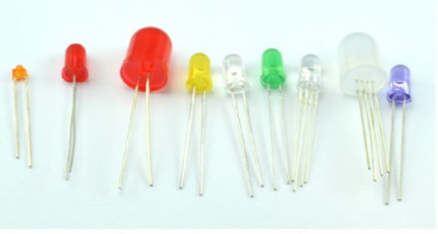
Controlling LED indicators is a task that's likely at the top of the to-do list for any electronics enthusiast. There's an incredible variety of LEDs available, ranging from the simplest to high-power LEDs and from infrared to ultraviolet.

The illustration showcases an assortment of LEDs with diverse current requirements. Some work perfectly fine with a digital output, while others require transistors or even entire electronic circuits for control.

Image

Conventional LEDs

Posted: 24 Jul 2024, 21:43
by robotwf
Standard LEDs

Standard LEDs are those familiar, multi-colored 5 mm (sometimes 10 mm or 3 mm) devices that light up with a relatively low current. This makes them suitable for direct control from an Arduino or Raspberry Pi output.

The illustration demonstrates how these LEDs are typically connected to the digital output of an Arduino or Raspberry Pi. A resistor is necessary here to limit the current passing through the LED, and there are two reasons for this: firstly, to avoid exceeding the LED's maximum current rating (otherwise, its lifespan will be short), and secondly, not to exceed the maximum output current on an individual board pin or cumulatively across all of its output pins.
Image

Current limitation

Posted: 24 Jul 2024, 21:50
by robotwf
Understanding LED Direct Voltage and Current

When an LED is connected as shown in the diagram above, the entire circuit will have a more or less constant voltage. This is referred to as the forward voltage of the LED. Depending on the LED's color, the forward voltage can vary; it's typically minimal for red LEDs and highest among all LEDs that emit visible light (see the table).

There are also infrared (IR) LEDs, similar to those found in TV remote controls, and ultraviolet (UV) LEDs, which are often used at parties to give white clothes a violet hue or to check the authenticity of banknotes.

In addition to the forward voltage, another important characteristic of an LED that you need to be aware of is the forward current you intend to pass through it. Most LEDs emit some light with a current as low as 1 mA or slightly less, but they typically reach their optimal brightness at around 20 mA. This is a relatively wide range, so for safety reasons, use a 470 Ohm resistor when working with any LED that you connect to an Arduino or Raspberry Pi, even though the LED may not shine as brightly as it could.

To calculate the resistance of the series resistor conveniently, you can use a special web service that will do the calculations for you. Such a service can be found at led.linear1.org/lled.wiz, and its interface is shown in the diagram below.

As you can see, the calculator assumes a power supply voltage of 3.3 V (obviously, this calculation is for Raspberry Pi), and the maximum current allowed for any Raspberry Pi pin is 16 mA. The calculator suggests that with these parameters, for an LED with a forward voltage of 2.2 V, you should use an 82 Ohm resistor.

If you prefer to perform this calculation manually, start by subtracting the LED's forward voltage value (2.2 V) from the power supply voltage of 3.3 V. This will result in 1.1 V. Then calculate the resistance of the resistor using Ohm's law: R = V / I = 1.1 V / 16 mA = 68.75 Ohms.

When selecting a resistor, you can also refer to the data in the table, which provides approximate forward voltage levels for LEDs of different colors.

Please note: the resistor values have been adjusted and approximated to standard resistor values that are readily available.

Note

In the IR column for the Raspberry Pi device (3.3 V; 3 mA), the symbol 'x' is indicated. Infrared LEDs for remote control devices usually require at least 10 mA to operate, and they are designed with a current rating of 100 mA or more - only at these values do they become sufficiently "long-range."


Image
Image

Traffic light

Posted: 24 Jul 2024, 22:30
by robotwf
Creating a Traffic Light with Arduino and Raspberry Pi

With such a fantastic selection of colorful LEDs, let's take red, yellow, and green emitters and create a traffic light controlled by Arduino or Raspberry Pi (see the diagram below).

The LEDs should light up in the following sequence:
1. Red.
2. Red with yellow.
3. Green.
4. Yellow.
Image
Components

For this project, you will need the following components to work with Arduino and Raspberry Pi:

- LED1 - Red LED
- LED2 - Yellow LED
- LED3 - Green LED
- R1-3 - 150 Ohm resistors
- A 400-point breadboard
- Male-to-male jumper wires
- Male-to-female jumper wires (for Raspberry Pi only)

Over time, you may start to select resistors with different values, but for this project, I suggest using 150 Ohm resistors for both Arduino and Raspberry Pi, and for LEDs of all three colors. If you want to achieve maximum brightness, consider selecting optimal resistors later on.

Overall Setup

Each of the three LEDs is connected to a separate output pin on Arduino or Raspberry Pi.

Connecting to Raspberry Pi

In the version of the project running on the Raspberry Pi, the 'male-to-male' jumpers are replaced with 'female-to-male' jumpers, and the breadboard is connected to GPIO pins 18, 23, and 24 in the same configuration.
Image

Raspberry Pi Program

Code: Select all

import RPi.GPIO as GPIO
import time

GPIO.setmode(GPIO.BCM)

red_pin = 18
orange_pin = 23
green_pin = 24

GPIO.setup(red_pin, GPIO.OUT)
GPIO.setup(orange_pin, GPIO.OUT)
GPIO.setup(green_pin, GPIO.OUT)

def set_leds(red, orange, green):    # (1)
    GPIO.output(red_pin, red)
    GPIO.output(orange_pin, orange)
    GPIO.output(green_pin, green)

try:         
    while True:
        set_leds(1, 0, 0)
        time.sleep(3)
        set_leds(1, 1, 0)
        time.sleep(0.5)
        set_leds(0, 0, 1)
        time.sleep(5)
        set_leds(0, 1, 0)
        time.sleep(0.5)
          
finally:  
    print("Cleaning up")
    GPIO.cleanup()
The function set_leds, defined in the line marked with comment 1, is used just like in the case of Arduino to avoid cluttering the main loop with multiple GPIO functions.
viewtopic.php?p=22#p22

PWM and LEDs

Posted: 24 Jul 2024, 22:33
by robotwf
Pulse Width Modulation (PWM) for LED Brightness Control

Attempting to control the brightness of an LED by varying the voltage across it usually does not yield satisfactory results. This is because there is a significant dead zone in the voltage range of the LED, and only after overcoming this zone does the voltage reach a level that allows the LED to emit some light. For controlling LED brightness, analog outputs with PWM (Pulse Width Modulation) work best (see "Pulse Width Modulation" below). LEDs can be turned on and off very quickly, much faster than in a millionth of a second. Using PWM, the LED appears to change brightness proportionally to how long it remains in the on state, although visually, this is perceived as a change in brightness.

Pulse Width Modulation (PWM)

Until now, we've been controlling devices in a very "digital" manner—turning them on and then off. But what if you need to control something more "analog," such as adjusting a motor's speed or an LED's brightness? For this, you need to learn how to control the power supplied to the device.

The technique underlying this kind of control is called Pulse Width Modulation (PWM). It involves using digital outputs that provide a series of high and low pulses. By controlling the fraction of time during which high pulses are applied, you can control the overall power supplied to the motor or LED.

The diagram illustrates how PWM works. It assumes that the voltage at the GPIO (General Purpose Input/Output) pin of the Raspberry Pi is 3.3 V. You will also need a transistor connected to the GPIO pin to provide enough current to control the motor.

The ratio of the pulse duration to its period is called the duty cycle. If the pulses correspond to the on state for only 5% of the entire cycle (duty cycle equals 5%), the motor will receive very little energy, and it will rotate very slowly (or the LED will emit a dim light). Increasing the duty cycle to 50% will provide half the power to the motor or LED, resulting in approximately half the maximum speed or brightness. If the duty cycle increases to 90%, the motor will rotate almost at full speed, and the LED will shine at full intensity.

To turn off the motor or LED, simply reduce the duty cycle to 0, and to achieve full power, raise it to 100%. Maintaining the GPIO pin in a high state continuously will result in a 100% duty cycle.

Both Arduino and Raspberry Pi allow you to use PWM on their output pins. On an Arduino Uno, it can only be enabled on pins D3, D5, D6, D9, D10, and D11—these pins are marked with a tilde (~) on the Arduino board itself. The PWM frequency on Arduino Uno for most pins is 490 Hz (pulses per second). Exceptions are pins 5 and 6, which operate at 980 Hz.

For controlling LED brightness or motor speed, a PWM frequency of 490 Hz, which is the default in Arduino, is perfectly adequate.
Image

RGB LEDs

Posted: 24 Jul 2024, 22:35
by robotwf
RGB LEDs: Shining a Light on Color Mixing

An RGB LED is a single assembly that actually contains three LEDs: one blue, one red, and one green. By using PWM to control the brightness of each of these LEDs, you can make the RGB LED display any of three colors.

Although an RGB LED contains three regular two-pin LEDs, it doesn't mean the LED package must have six pins. You can connect one pin from each LED together to make it appear as a single pin.

If you connect the negative pins of all LEDs together, the resulting pin is called the common cathode, and if you do the same with the positive pins, you get the common anode.

Image

RGB LEDs can emit both directional and diffused light. In a directional LED, the red, green, and blue LEDs are clearly distinguishable, and their colors don't mix much. In diffused assemblies, the colors of the three LEDs blend together much better.

Next, we'll be working with displays based on RGB LEDs that have their own control microchip. This chip limits the current to the red, green, and blue LEDs and also serves as a serial data interface. Arduino or Raspberry Pi can control many such LEDs through this interface, using just one output pin.

Color mixing

Posted: 24 Jul 2024, 22:59
by robotwf
Experiment: Controlling RGB LEDs with Arduino and Raspberry Pi

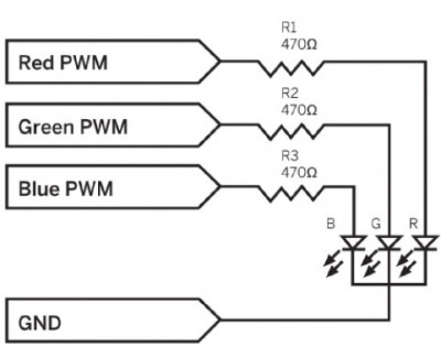
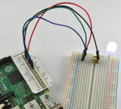
In this experiment, we will control the color of an RGB LED using both Arduino and Raspberry Pi. In the version of the experiment performed on Raspberry Pi, we will use a graphical user interface with three sliders to control the color. The images below depict the Raspberry Pi setup and the experiment's schematic.
Image
Image

Components

For this experiment, you will need the following components for both Arduino and Raspberry Pi:

LED1 - RGB LED
R1-3 - 470 Ohm 0.25W resistors
400-point breadboard
Male-to-Male jumper wires
Male-to-Female jumper wires (only for Raspberry Pi)

Please note that Male-to-Female jumper wires are only needed for connecting to the GPIO pins on Raspberry Pi (if you plan to conduct this experiment with Raspberry Pi as well).

To achieve optimal brightness and the best color balance, careful selection of resistors with matching resistances is essential. However, it's easier to obtain the components if you use 470 Ohm resistors for all three channels. They will work with both Raspberry Pi and Arduino.

Connecting to Raspberry Pi

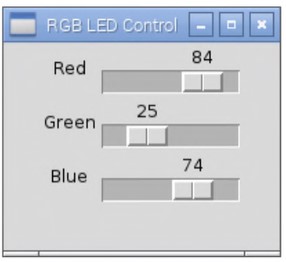
In the version of the experiment focused on Raspberry Pi, we will not just enter commands to change the color, but we will use a small window with a user interface containing three sliders – one for each color channel. As you adjust the position of the sliders, the color of the RGB LED will change.

Since this program features a graphical user interface, and there is no graphical interface in SSH, you will need to connect a keyboard, mouse, and monitor to the Raspberry Pi.

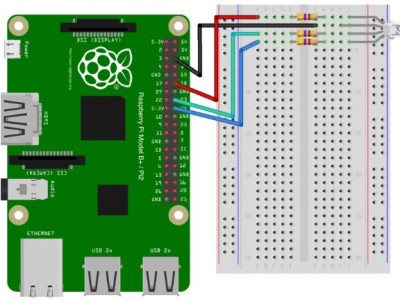
The layout of the breadboard for working with Raspberry Pi is shown in the figure – it is exactly the same as in the case of Arduino, except that when working with Raspberry Pi, you will need ‘male-to-female’ jumper wires. The GPIO pins 18, 23, and 24 are used as PWM outputs here.
Image

Program for Raspberry Pi.

The program for this experiment, written in Python, utilizes the Tkinter framework. This allows for the creation of window applications with their own controls, enabling you to move beyond the primitive command line you have been working with so far. Consequently, the code of the program turns out to be a bit longer than usual. Additionally, it sometimes employs relatively complex programming.

Let's take a look at the code:

Code: Select all

from Tkinter import *       
import RPi.GPIO as GPIO
import time


GPIO.setmode(GPIO.BCM)  # (1)
GPIO.setup(18, GPIO.OUT)
GPIO.setup(23, GPIO.OUT)
GPIO.setup(24, GPIO.OUT)


pwmRed = GPIO.PWM(18, 500) # (2)
pwmRed.start(100)

pwmGreen = GPIO.PWM(23, 500)
pwmGreen.start(100)

pwmBlue = GPIO.PWM(24, 500)
pwmBlue.start(100)

class App:
    
    def __init__(self, master): #(3)
        frame = Frame(master)  #(4)
        frame.pack()
        
        Label(frame, text='Red').grid(row=0, column=0) # (5)
        Label(frame, text='Green').grid(row=1, column=0)
        Label(frame, text='Blue').grid(row=2, column=0)
        
        scaleRed = Scale(frame, from_=0, to=100,     # (6)
              orient=HORIZONTAL, command=self.updateRed)
        scaleRed.grid(row=0, column=1)
        scaleGreen = Scale(frame, from_=0, to=100,
              orient=HORIZONTAL, command=self.updateGreen)
        scaleGreen.grid(row=1, column=1)
        scaleBlue = Scale(frame, from_=0, to=100,
              orient=HORIZONTAL, command=self.updateBlue)
        scaleBlue.grid(row=2, column=1)

    def updateRed(self, duty):     # (7)
        # change the led brightness to match the slider
        pwmRed.ChangeDutyCycle(float(duty))

    def updateGreen(self, duty):
        pwmGreen.ChangeDutyCycle(float(duty))
    
    def updateBlue(self, duty):
        pwmBlue.ChangeDutyCycle(float(duty))


root = Tk()  # (8)
root.wm_title('RGB LED Control')
app = App(root)
root.geometry("200x150+0+0")
try:
    root.mainloop()
finally:  
    print("Cleaning up")
    GPIO.cleanup()
Let's clarify some points of this program step by step, using the line layout made in the comments:
  • We will configure the Raspberry Pi to work with pin names according to the Broadcom system, rather than just with positional designations.
  • We will start Pulse Width Modulation (PWM) on the red, green, and blue channels to control the brightness of the LEDs.
  • This function is called when the application is created.
  • This frame contains various controls from the graphical user interface.
  • We create labels and place each one in its own grid cell.
  • We create sliders and place each one in its own grid cell. The command attribute specifies which method should be called when the slider is moved.
  • This method and similar methods for other colors are triggered when the slider is moved.
  • We launch the graphical user interface, setting the window title, size, and position.
We load and run the program.

We will run the program with administrator privileges using the following command:
$ sudo python mixing_colors.py
After a couple of seconds, a window will appear as shown in the figure. As the sliders are moved, the color of the RGB LED will change.
Image