Motors, pumps and actuators

  • Equipment

    In this experiment, the same equipment is used as in the "Experiment: Controlling a DC Motor" section (viewtopic.php?p=14#p14). However, here you won't just turn the motor on and off; you'll also control its speed.

    If you haven't done so already, assemble the circuit from the "Experiment: Controlling a DC Motor" section (viewtopic.php?p=14#p14). As a reminder, the layout of the prototype board for this experiment is shown in the image below.

    Image

    Connecting Raspberry Pi

    Connect the breadboard to the Raspberry Pi as shown in the image below: using jumper wires "female-male," connect the ground from the breadboard to one of the GND pins on the GPIO header, and the control wire from the breadboard to pin 18 of the Raspberry Pi.
    Image

    Raspberry Pi Program

    The program for Raspberry Pi is fundamentally similar to Arduino code. In our case, the program will prompt you to enter duty cycle values and thus control pin 18.

    Code:

    Code: Select all

    import RPi.GPIO as GPIO
    import time
    
    GPIO.setmode(GPIO.BCM)
    
    control_pin = 18     # (1)
    
    GPIO.setup(control_pin, GPIO.OUT)
    motor_pwm = GPIO.PWM(control_pin, 500)  # (2)
    motor_pwm.start(0)                      # (3)
    
    try:         
        while True:                         # (4)
            duty = input('Enter Duty Cycle (0 to 100): ')
            if duty < 0 or duty > 100:
                print('0 to 100')
            else:
                motor_pwm.ChangeDutyCycle(duty)
            
    finally:  
        print("Cleaning up")
        GPIO.cleanup()
    Let's clarify some aspects of the program by breaking it down into points, using line comments:
    • The initial part of the code is exactly the same as the code from the "Experiment: Controlling an Electric Motor" section, but then pin 18 is defined as an output.
    • Pin 18 is set as a PWM output in this line (the RPi.GPIO library allows any GPIO pin to be set as a PWM output). The parameter 500 means that the PWM frequency is 500 Hz (pulses per second).
    • The PWM output will not start working until the start function is called. Its parameter is the initial duty cycle value, and since we start with the motor turned off, this value is 0.
    • In the main loop, you are prompted to input a duty value using input, and then it checks which range it falls into. If it is within the range of 0 to 100, it is used as the duty cycle in the ChangeDutyCycle function.
    Uploading and Running the Program

    Run the program as an administrator using the sudo command, and then try entering various duty cycle values. The motor speed should change, just like it does with Arduino:

    Code: Select all

    pi@raspberrypi ~/make_action/python $ sudo python pwm_motor_control.py
    Enter Duty Cycle (0 to 100) : 50
    Enter Duty Cycle (0 to 100) : 10
    Enter Duty Cycle (0 to 100) : 100
    Enter Duty Cycle (0 to 100) : 0
    Enter Duty Cycle (0 to 100) : 
  • Using Relays with Arduino or Raspberry Pi

    If you intend to intermittently turn a motor on and off using Arduino or Raspberry Pi, you can employ relays. While this approach may be considered somewhat old-fashioned, it has several advantages:

    - It is straightforward to implement and requires minimal components.
    - It provides excellent isolation between the high-current motor, which generates a lot of noise, and the delicate construction of the Pi and Arduino.
    - It enables you to work with high currents (when the relay is selected correctly).
    - Ready-made relay modules are available that can be used directly with Raspberry Pi or Arduino.

    However, there are some drawbacks to working with relay modules:

    - They are relatively bulky.
    - They can only turn the motor on or off, not control its speed.
    - Since relays are electromechanical devices, they typically endure no more than 10 million switching operations before something breaks.

    Electromechanical Relays

    The image below displays perhaps the most common type of relay, often referred to as a "sugar cube" relay due to its shape, though typically these relays are black, not the color of actual sugar cubes.

    When a current (typically around 50 mA) flows through the relay coil, it acts as an electromagnet and attracts two contacts towards each other, creating a connection between them. These contacts are designed to handle high voltage and current, capable of switching tens of amperes.

    Image

    Although we'll use relays to control a DC motor, the relay itself functions as a simple switch, allowing you to control almost anything with it.

    These types of relays are called "single-pole changeover" relays (abbreviated as SPCO), as they have not just two contacts that can be either closed or open, but three: the common contact (usually labeled COM) and two other contacts: normally open (NO) and normally closed (NC). In this context, "normally" means "without power applied to the relay coil." Therefore, NO and COM contacts will be open (not connected) until the relay coil is energized. The normally closed contact operates in the opposite manner, where the NC and COM contacts are closed by default but will disconnect when the relay coil is energized.

    In standard situations, only two relay contacts—NO and COM—are used to control the connected device.

    Using Relays with Arduino or Raspberry Pi

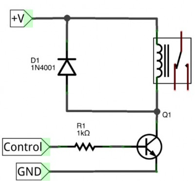
    When using relays with Raspberry Pi or Arduino, you will need relays designed for a 5V coil voltage. Relay coils consume too much current (around 50 mA) to be controlled directly by Raspberry Pi or Arduino, so in both cases, you'll need to include a small transistor in the circuit to manage the relay coil at 5V.
    Image

    As mentioned, the relay coil is designed to operate at 5V and requires approximately 50 mA of current, which is too much for Arduino and excessive for a Raspberry Pi GPIO pin. Therefore, similar to what we did in the "Experiment: Controlling a DC Motor" section, we'll use a transistor to control the relay coil, with the relay coil acting as the "load" instead of the motor.

    This setup is practical only when the motor (or any other load you want to control) consumes a significant amount of current, making it unsuitable for direct control using just a transistor.

    Like the motor, when relays are switched on and off, they can produce voltage spikes, so it's necessary to include a diode in the circuit.

    It's evident that in the circuit shown above, the switching part of the relay is electrically isolated from the part with the coil. This reduces the likelihood of electrical interference, voltage spikes, and other harmful electrical phenomena reaching your Arduino or Raspberry Pi.

    Since a relay powered by a 5V coil requires only about 50 mA of current, a budget transistor like 2N3904 will suffice in our case.

    Relay Modules

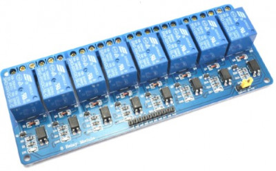
    If you have multiple devices you want to control, and they adhere to the previously mentioned limitation of relay-based control (typically limited to on/off switching), it would be convenient to acquire a relay module, like the one shown in Fig. 7.9.
    Image

    These modules are inexpensive and can be readily purchased on online marketplaces like AliExpress. They typically come with the relays themselves, transistors to control them, and small LEDs to help identify which specific relay is activated. Given their setup, such relay modules can be connected directly to Raspberry Pi or Arduino.

    Relay modules may contain varying numbers of relays, from a single relay to eight or more. Usually, relay modules have the following contacts:

    - GND - Ground.
    - VCC or 5V - Connect this contact to the 5V pin on Raspberry Pi or Arduino; when you activate it, it can supply voltage to the relay coils.
    - Data pins - Each data pin controls one of the relays. Sometimes these pins may be active high, meaning they activate the relay when transitioning to a high state. In other cases, the data pin may be active low, activating the relay when the GPIO pin goes low.

    Additionally, relay modules feature screw terminals connected directly to the working relay contacts that close the power circuits of the controlled devices.
  • Using Relays to Control a DC Motor

    In this experiment, we will simply turn a DC motor on and off using relays.

    A ready-made relay module with eight relays is used here, but for our experiment, we will need just one relay. So, if you prefer, you can use a module with fewer relays.

    Components

    For this experiment with Arduino and Raspberry Pi, you will need the following components:
    - Small direct current (DC) motor with a 6V power supply
    - Relay module
    - 4xAA battery holder (6V)
    - Jumper wires compatible with the relay module

    Some relay modules connect to Arduino or Raspberry Pi using connectors, while others use pins, so choose appropriate jumper wires. This means that to connect the relay module to Arduino using pins, you will need "male-to-female" jumper wires, and for connecting it to Raspberry Pi, you will need "female-to-female" jumper wires.

    Experiment Setup

    The experiment setup is illustrated in the diagram below. The relay contacts act as switches, each of which can be in one of two positions. As mentioned earlier, there are common, normally open (NO), and normally closed (NC) contacts. When the relay coil is not energized, the common contact is connected to the normally closed contact. When power is supplied to the coil, the switch's position changes, and the common contact connects to the normally open contact.
    image.png
    The programs for this experiment on Arduino and Raspberry Pi are almost identical to those we used in the "Experiment: Controlling a DC Motor" section. The only difference arises if your module has an active-low logic, like the one I worked with.

    Raspberry Pi Program

    Code: Select all

    import RPi.GPIO as GPIO
    import time
    
    GPIO.setmode(GPIO.BCM)
    
    control_pin = 18
    
    GPIO.setup(control_pin, GPIO.OUT)
    
    try:         
        while True:
            GPIO.output(control_pin, False)  
            time.sleep(5)                 
            GPIO.output(control_pin, True) 
            time.sleep(2)                 
            
    finally:  
        print("Cleaning up")
        GPIO.cleanup()
    
    Please note that the Raspberry Pi program uses the GPIO library to control the GPIO pins. Adjust the `control_pin` variable to match the GPIO pin you have connected to the relay module's control input.

    Remember to handle the power supply and connections with care to ensure safe experimentation.
  • Linear actuators transform the rotation of a direct current motor into linear motion. Such devices are often used for remotely opening and closing windows and doors.

    In linear actuators, the key component is a threaded drive rod onto which a peculiar nut is threaded. This nut cannot rotate but freely moves up and down the rod when it rotates, thus moving the working part of the actuator (shaft) forward and backward. The figure below illustrates how this works.

    Image

    Linear actuators move the shaft relatively slowly because the threaded rod and nut effectively act as a gearbox, and a standard gearbox is usually installed on the motor's side. Due to the low speed but the considerable power of a direct current motor, a linear actuator typically provides strong thrust or push. The mechanism shown in the figure generates a force of 1500 N (newtons), equivalent to lifting a load of 150 kg. Under full load, a similar linear actuator's motor can draw 5 A of current at 12 V.

    Image

    Typically, the motor of a linear actuator receives power through an H-bridge with a maximum current capacity of at least 5 A, enabling it to rotate in both directions. To prevent damage to the linear actuator when the nut reaches one end of the threaded rod, such devices are usually equipped with limit switches that automatically cut off power as soon as the nut hits one end. This simplifies motor control since you can set the H-bridge to power the motor in either direction for a limited time, allowing the mechanism to travel the entire distance backward or forward.
  • Solenoids are often used in conjunction with door latches and simple water valves. Similar to linear actuators, they provide linear motion for the rod (plunger) inside them, but a solenoid is a much simpler device. In fact, it's an electromagnet that facilitates the linear motion of the rod. The path it travels inside the solenoid is usually very short, mere centimeters.

    Under the influence of an electric current, the solenoid coil is energized, and magnetic forces push the rod, overcoming spring compression. When power to the coil is cut off, the rod freely returns to its initial position due to the spring's action. The principle of how a solenoid works is illustrated in the figure below.

    Image

    A solenoid-based regulating water valve, as shown in the figure below, is designed to switch the flow of pressurized tap water. When there is no power supplied to the valve, water does not flow through it. However, when the coil is energized, the plunger moves backward, allowing water to flow freely through the valve as long as it is powered.

    Image

    This 12-volt device is commonly used in household washing machines. Models of such valves designed to work with alternating current at 120 V or 220 V can also be found and are used in household applications. Working with higher voltage in contact with water can be dangerous, so I strongly recommend using 12-volt pumps and valves for your projects.