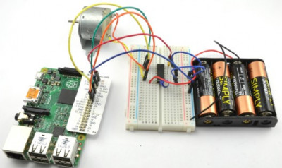
In this experiment, we will be using the L293D microchip, placing it on a prototype board. The assembled experiment circuit includes the prototype board with the L293D microchip, Raspberry Pi, a direct current motor, and a power source, as shown in the figure below:
 Components
For this experiment with Arduino and Raspberry Pi, you will need the following components:
IC1 - L293D H-Bridge Microchip
C1 - 100nF Capacitor
C2 - 16V 100µF Capacitor
M1 - Small DC Motor with a 6V power supply
Battery compartment for 4 AA batteries (6V)
400-point solderless prototype board
Male-to-Male Jumper Wires
Male-to-Female Jumper Wires (only for Raspberry Pi)
Experiment Circuit
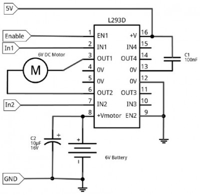
The circuit for this experiment is shown in the figure below. Raspberry Pi or Arduino provides a control voltage of 5V to the logic pin 16 of the L293D microchip. Power for the motor is supplied from a 6-volt battery pack to its pin 8.
Practically, only one of the H-bridges of the microchip is used here, so its pin EN2 is connected to ground to deactivate the unused part.
The pins EN1, IN1, and IN2 are connected to the digital output pins of Raspberry Pi or Arduino.
 CAPACITORS
As previously mentioned, using capacitors in the experiment is not necessary if we are only experimenting with this circuit for a few hours, as we are not primarily concerned with the reliability that capacitors could provide.
The capacitor positions shown in the diagram are quite typical for an H-bridge integrated circuit. Capacitor C1 is called a decoupling capacitor. It should be placed as close as possible to the microchip, between the logic signal and ground. The capacitance of capacitor C1 should not exceed 100nF (which is very small), but it helps eliminate various electrical noise that could potentially harm the logic of the microchip.
Capacitor C2 serves as an energy reservoir, which can provide power for some time, but this energy is specifically used to power the motor and is not consumed by the switching logic. The capacitance of this capacitor is usually much higher than that of C1, typically 100µF or more.
Prototype Board Layout
Before connecting the H-bridge to Arduino or Raspberry Pi, you can experiment with the circuit in standalone mode: check both the motor and the switching logic by powering them from the same 6-volt battery pack. This option is perfect if you want to test the microchip's operation without connecting it to Arduino or Raspberry Pi. However, when it comes to using the H-bridge with Arduino or Raspberry Pi, it's better to separate the power supply. The motor should receive power from the battery pack, while the logic of the microchip should be powered by Arduino or Raspberry Pi.
The figure below demonstrates the layout of the prototype board for autonomous testing. For working with Arduino or Raspberry Pi, you will hardly need to modify this layout; you will just need to rearrange some jumpers.
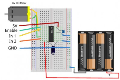
When placing components on the prototype board, pay special attention to the microchip. It must be positioned correctly: a small cut on one side should be directed towards the upper part of the prototype board in row 10. To the left and above this cut, you should find pin 1.
Now you can connect the battery. Initially, the motor should not rotate.
CLOCKWISE AND COUNTERCLOCKWISE
When I mention that my motor is rotating clockwise or counterclockwise, your motor may actually rotate in the opposite direction. If your motor rotates counterclockwise when I say it should rotate clockwise, it's not a problem because it will rotate clockwise when I say "counterclockwise."
If you want your motor's rotation to match the description, you can swap the connecting wires.
Sometimes it can be difficult to determine in which direction the motor is rotating because it's just a bare metal shaft. You can simply touch it; if you gently grip the shaft with your thumb and index finger, you will understand the direction of rotation. You can also cut a short strip of colored adhesive tape and attach it to the spindle to serve as a makeshift flag.
Standalone Experiment
Regardless of the direction in which the motor should rotate - clockwise or counterclockwise, the Enable contact must be connected to +V. To make the motor rotate, for example, clockwise, connect the free end of the jumper that is already connected to IN1 to +V, and connect IN2 to the row labeled GND located on the right side of the prototype board.
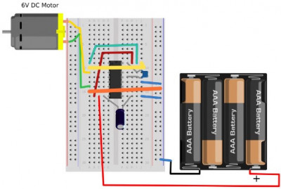
Now, we are going to reverse the motor's direction. You can leave the connection to Enable untouched, but you need to change the connections to IN1 and IN2 so that IN1 is now connected to GND, and IN2 is connected to +V, as shown in the diagram.
Please note: in the diagrams, IN1 and IN2 jumpers are depicted as thicker for easier differentiation from other jumpers.
Now that we have confirmed that the H-bridge is working as expected, we can connect our circuit to Raspberry Pi.
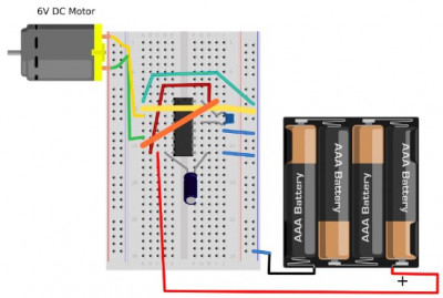 Connecting Raspberry Pi
The advantage of using an integrated H-bridge chip like L293D is that its control pins for motor operation require very low current. Its specifications state that the current should always remain below 100 μA (0.1 mA), which means you can easily use Raspberry Pi pins designed for low currents.
If you have both a Raspberry Pi and Arduino and have just completed the Arduino part of the experiment, preparing the breadboard for use with Raspberry Pi requires simply replacing the "male-to-male" jumper wires (which we used to connect to the Arduino breadboard) with "female-to-female" wires and connecting them to the GPIO header on the Raspberry Pi.
The diagram shows how to connect Raspberry Pi to the breadboard, and the fully functional motor control system with Raspberry Pi was shown above.
 Raspberry Pi Program
Code: Select all
import RPi.GPIO as GPIO
import time

GPIO.setmode(GPIO.BCM)

enable_pin = 18    # (1)
in_1_pin = 23
in_2_pin = 24

GPIO.setup(enable_pin, GPIO.OUT)
GPIO.setup(in_1_pin, GPIO.OUT)
GPIO.setup(in_2_pin, GPIO.OUT)
motor_pwm = GPIO.PWM(enable_pin, 500)
motor_pwm.start(0)

def forward(duty):          # (2)
    GPIO.output(in_1_pin, True)
    GPIO.output(in_2_pin, False)
    motor_pwm.ChangeDutyCycle(duty)

def reverse(duty):          # (3)
    GPIO.output(in_1_pin, False)
    GPIO.output(in_2_pin, True)
    motor_pwm.ChangeDutyCycle(duty)

def stop():
    GPIO.output(in_1_pin, False)
    GPIO.output(in_2_pin, False)
    motor_pwm.ChangeDutyCycle(0)

try:
    while True:        # (4)
        direction = raw_input('Enter direction letter (f - forward, r - reverse, s - stop): ')
        if direction[0] == 's':
            stop()
        else:
            duty = input('Enter Duty Cycle (0 to 100): ')
            if direction[0] == 'f':
                forward(duty)
            elif direction[0] == 'r':
                reverse(duty)

finally:
    print("Cleaning up")
    GPIO.cleanup()
This code is heavily based on Python code examples from other experiments. Let's clarify some points in the program based on the line comments:
1. At the top of the program, you'll find the typical GPIO setup and pin definitions. The Enable pin on the L293D is used for motor speed control, so the pin connected to it, pin 18, is configured as a PWM output.
2. The
forward function sets up the IN1 and IN2 pins to control the motor's direction and then sets the duty cycle for the PWM channel.
3. Comparing it to the
reverse function, you'll notice that the values for IN1 and IN2 pins have swapped places. The
stop function halts the operation of the control pins (both are set to
LOW), and the duty cycle becomes 0.
4. The main
while loop prompts the user to enter a command, and based on the command, it calls the
stop,
forward, or
reverse function.
Loading and Executing the Program
Launch the program with administrator privileges using the
sudo command, and you'll see that it operates much like its Arduino counterpart, allowing you to set the motor's speed and direction.
Code: Select all
$ sudo python full_motor_control.py
Enter direction letter (f - forward, r - reverse, s - stop): f
Enter Duty Cycle (0 to 100): 50
Enter direction letter (f - forward, r - reverse, s - stop): f
Enter Duty Cycle (0 to 100): 100
Enter direction letter (f - forward, r - reverse, s - stop): s
Enter direction letter (f - forward, r - reverse, s - stop): r
Enter Duty Cycle (0 to 100): 50
Enter direction letter (f - forward, r - reverse, s - stop): r
Enter Duty Cycle (0 to 100): 100
Enter direction letter (f - forward, r - reverse, s - stop): s
Enter direction letter (f - forward, r - reverse, s - stop):
HANDLE THE MOTOR WITH CAUTION
Imagine what would happen if a car were moving at full speed and then suddenly went into reverse. In the case of small motors with no massive components attached, this usually doesn't cause problems. However, when working with Arduino or Raspberry Pi powered from the same source as the motor, you may find that Raspberry Pi abruptly shuts down, and Arduino resets. This occurs because when changing directions suddenly, there is a very high current draw, causing a sharp drop in electrical power.
For large motors, a sudden change in speed or direction of a massive component with significant inertia can lead to serious issues. Not only can the increased currents potentially damage the H-bridge, but the motor's bearings can also experience mechanical stress.
This should be considered when developing control software for relatively large motors. To handle the motor gently, it's better to stop it before changing direction (create a delay during which it truly comes to a halt) and then start it again in the opposite direction. If you're using auxiliary functions like
forward and
reverse from the section "Experiment: Controlling Motor Direction and Speed," your code might look something like this in Arduino:
Code: Select all
forward(255);
delay(200);
reverse(255);
