Servo motors respond very quickly to position change commands. In t
his project, this property is used to pull the puppet's strings and make it dance or move in any desired direction.
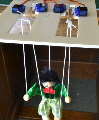
The control of the servo drives is based on step-by-step playback of a list of positions of their working parts. In the section "Project: Pepe Doll finds his voice," the puppet will be able to speak, and in the future, thanks to the Internet connection, it will be able to perform a dance specified by a particular hashtag.
Components
For this project on a Raspberry Pi, you will need the following components:
16-channel 12-bit PWM/Servo driver module
4 x 9g servo motors
Adapter with a round socket and screw clamps
Female-to-female jumper wires
Male-to-male jumper wires
5V 2A power supply
4 toothpicks (approximately 7-8 cm each)
Small puppet (with strings for each limb)
A sheet of mounting cardboard, A4 size
Hot glue gun or epoxy glue and a drill
Project scheme
The Raspberry Pi is mainly used in the project so that it can be connected to the Internet, as will be shown later. However, Arduino can also be used. In this case, external Adafruit PWM/Servo modules will not be needed, and the servo motors will need to be connected to Arduino using a breadboard and male-to-male jumper wires. However, you will need a bunch of these jumper wires!
The puppet's arms and legs are controlled by four 9g servo motors - one for each arm and leg. The servo motors are controlled using a 16-channel PWM/Servo controller board from Adafruit. An additional advantage of this design is that the connectors on the servo motor wires can be directly connected to the connectors on the controller board (in the diagram, only the middle wire from each servo motor to the board is shown to avoid confusion).
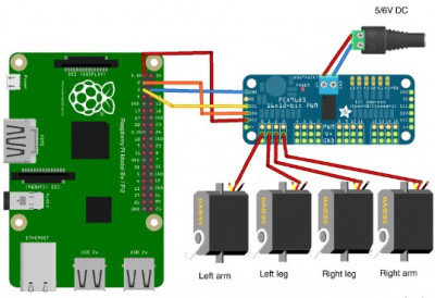
The simultaneous operation of four servo motors requires the use of a separate battery pack for their power supply. This is necessary to reduce the interference from the motors on the operation of the Raspberry Pi.
The length of the plastic swing arms supplied with the servo motors for our project is insufficient, so to ensure the full range of motion of the puppet's arms and legs, it is necessary to extend the servo motor arms using toothpicks.
Assembly of the project
In this project, creating a dancing puppet requires a lot of mechanics, electronics, and programming. Below are the steps necessary to implement the project.
Step 1: Extending the servo motor arms
The servo motors come with a small packet of various plastic swing arms that can be installed on the output shaft of the servo motor. Choose a straight swing arm and glue a toothpick to it as shown in the diagram below. A hot glue gun or epoxy glue works well for this purpose.
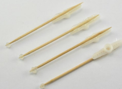
Note that a drop of glue is left at the end of each toothpick. This is necessary to prevent the puppet strings from slipping when they are attached to the end of the toothpick.
Step 2: Making the chassis
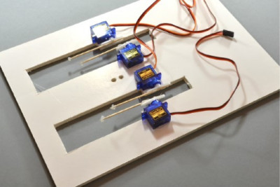
To control the movement of the puppet's limbs, the swing arms of the four servo motors must be able to move freely up and down. To place everything in the right positions, make cuts on a suitable mounting panel (photo sticker cardboard works well).
To accurately determine the locations of the cuts, use a template. Place the printed template from the file on the mounting panel and attach it lightly with glue so that it can be removed before attaching the servo motors to this panel.


After making two large cuts in the panel with a utility knife according to the template, also drill two small holes that are needed for the strings going to the puppet's head and bearing its weight.
 Step 3: Attaching the servo motors
Remove the paper template from the mounting panel and attach the extended swing arms to the output shafts of the servo motors. Attach the swing arms not too tightly so that they can be removed if needed to adjust the servo motor's position.
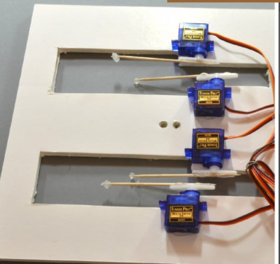
Align the servo motors so that all swing arms can move freely and do not interfere with each other. Before gluing the servo motors, remove the labels from them, as the servo motors will adhere better.
Step 4: Puppet Preparation
The diagram shows the puppet that we will control in this project. One string is attached to the top of the puppet's head, bearing the weight of the puppet. This string should be passed through the two holes drilled in the mounting panel (chassis) and tied underneath it.
Each leg of the puppet is attached to a separate string, and the arms are connected together by a string that is attached to one of the shoulders of the wooden crossbar. Preliminary, oyu need to cut the strings going from the hands to the shoulders of the crossbar, and pass them through a hole in one of the shoulders, then tie them together. To prevent the cut ends of the nylon strings from fraying, they should be melted using a match or a hot hairdryer. It is better, if possible, not to cut the strings, but to untie their ends that are attached to the wooden crossbar.
Before attaching the puppet to the new structure, it is necessary to connect all the servo motors and run the programs to set the swing arms of all the servo motors in the correct position.
 Step 5: Connecting the wires
It is best to orient the Raspberry Pi board so that the (I^2)C interface connector is on the opposite side from the servo controller module. This will be more convenient when using equipment when Pepe gains a voice.
If you want to reduce the amount of soldering, you can limit yourself to soldering only the four connectors for the servo motors, as in this project only four are involved. After connecting the wires according to the diagram shown above, everything should look as shown in the diagram below.
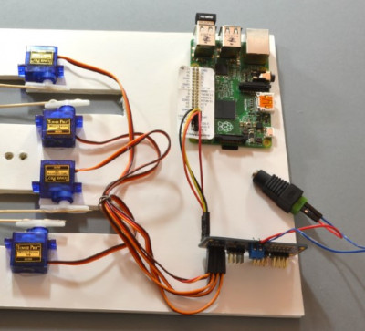
Make sure to correctly connect the connectors of all the servo motors: the orange control wire should be at the top, and the brown or black ground wire (GND) should be at the bottom.
Now you can connect the 5V power supply for the servo motors and a separate power supply for the Raspberry Pi through the USB connector.
Step 6: Running the test program
To set the servo motors in the correct position, you need to use a separate program that allows you to set the swing arms of all servo motors at a specific angle.
Code: Select all
#!/usr/bin/python

from Adafruit_PWM_Servo_Driver import PWM
import time

# ===========================================================================
# Example Code
# ===========================================================================

# Initialise the PWM device using the default address
pwm = PWM(0x40)
# Note if you'd like more debug output you can instead run:
#pwm = PWM(0x40, debug=True)

servoMin = 150  # Min pulse length out of 4096
servoMax = 600  # Max pulse length out of 4096

def map(value, from_low, from_high, to_low, to_high):
  from_range = from_high - from_low
  to_range = to_high - to_low
  scale_factor = float(from_range) / float(to_range)
  return to_low + (value / scale_factor)


def set_angle(channel, angle):
  pulse = int(map(angle, 0, 180, servoMin, servoMax))
  pwm.setPWM(channel, 0, pulse)

pwm.setPWMFreq(60)                        # Set frequency to 60 Hz
while (True):
  angle = input("Angle:")
  set_angle(0, angle)
  set_angle(1, angle)
  set_angle(2, angle)
  set_angle(3, angle)
The Adafruit servo motor module uses the (I^2)C interface, which is disabled by default on the Raspberry Pi.
SETTING UP (I^2)C ON RASPBERRY PI
First, make sure your package manager is up to date by running the following command:
$ sudo apt-get update
Next, launch the
raspi-config configurator:
$ sudo raspi-config
In the menu that appears, select
Advanced, then
(I^2)C. You will be asked,
Would you like the ARM I2C interface to be enabled? Choose
Yes. You will then be asked,
Would you like the I2C kernel module to be loaded by default? In this case, the appropriate choice is
Yes. Select
Finish to exit the raspi-config configurator.
Run the following command from your home directory to install some useful tools for (I^2)C:
sudo apt-get install python-smbus i2c-tools
To verify that the Raspberry Pi is connected to the Adafruit servo motor board and ready to work, you can run the following command:
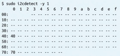
$ sudo i2cdetect -y 1
You should see the following result (the numbers 40 and 70 in the table indicate that the board is connected):
After setting up the (I^2)C interface, remove the swing arms from the servo motor shafts and run the program provided above. When prompted, enter the angle value of
90
$ sudo python set_servos.py
Angle: 90
Angle:
The servo motors should buzz and rotate to the 90° angle. Now you can attach the swing arms as close to horizontal as possible, as allowed by the teeth on the servo motor shafts.
Step 7: Connecting the puppet
Now that all the servo motors are set at 90°, tie the string coming from the puppet's head to the holes in the center of the chassis. Then tie the strings coming from the puppet's limbs to the extended swing arms of the servo motors. Attach the strings in a way that the arms and legs are in a halfway raised position.
You can now run the program again and, by entering different angles, check if the puppet's limbs cover the maximum range of movements.
Raspberry Pi program
The program for this project can be considered just a starting point. It uses an array of servo motor position values, where you can input your own values to control the puppet's movements. The main "dance" is somewhat rudimentary, but it can hardly be called elegant.
You can run the program even before looking at the code.
Code: Select all
from Adafruit_PWM_Servo_Driver import PWM   # 1
import time

pwm = PWM(0x40)

servoMin = 150  # Min pulse length out of 4095     # 2
servoMax = 600  # Max pulse length out of 4095

dance = [      # 3
  #lh  lf  rf  rh
  [90, 90, 90, 90],
  [130, 30, 30, 130],
  [30, 130, 130, 30]
]

delay = 0.2   # 4

def map(value, from_low, from_high, to_low, to_high):  # 5
  from_range = from_high - from_low
  to_range = to_high - to_low
  scale_factor = float(from_range) / float(to_range)
  return to_low + (value / scale_factor)


def set_angle(channel, angle):  # 6
  pulse = int(map(angle, 0, 180, servoMin, servoMax))
  pwm.setPWM(channel, 0, pulse)

def dance_step(step):  # 7
  set_angle(0, step[0])
  set_angle(1, step[1])
  set_angle(2, step[2])
  set_angle(3, step[3])


pwm.setPWMFreq(60)   # 8


while (True):   # 9
  for step in dance:
      dance_step(step)
      time.sleep(delay)
Let's clarify some points of the program step by step, using the line annotations made in the comments:
1. The Adafruit board can be used not only to control servo motors, but also other devices that accept PWM signals, such as LEDs. That's why the code imports a class called
PWM.
2. Two constants,
servoMin and
servoMax, set the pulse duration between
0 and
4095, where
4095 corresponds to
100% duty cycle.
3. The
dance array contains three sets of data for a specific dance. You can add as many lines as you want. Each line consists of an array of four values. This is the angle of rotation for the left hand, left leg, right leg, and right hand respectively. Since the servo motors for the arms and legs are mounted mirror-wise to each other, an angle greater than 90° means raising the arm but lowering the leg (this should be considered when creating your own original dance).
4. The
delay variable sets the pause between each dance step. The smaller its value, the faster the puppet will move.
5. The
map function is used to scale the angle value to the right (maximum) pulse duration value when used in the
set_angle function.
6. The
set_angle function has two parameters: the first one sets the servo motor channel number (from 0 to 3), and the second one sets the angle of rotation.
7. The
dance_step function sets the angles for the four limb servo motors and moves each servo motor to the specified angle.
8. Setting the PWM frequency to
60 times per second provides a series of pulses every 17 microseconds, which is approximately what the servo motor needs.
9. In each iteration of the main program loop, one step in the dance is performed - the servo motors are set to the specified angles, followed by a pause before the next step. When all the steps specified in the program are completed, it starts over.
Let Pepe not only dance...
Try changing the contents of the dance data array to create your own puppet movements. You can try to make the puppet walk, perform wave-like motions, or stand on one leg. Setting a slightly longer delay between steps provides more opportunities to observe the puppet's movements and make adjustments to the dance data array.