Turning off the heater when the temperature sensor indicates that the heater is hotter than the set temperature and turning it on when it's cooler than that leads to a system where the temperature "oscillates" around the set value.
For more precise temperature control, proportional-integral-derivative (PID) control should be used.
Instead of simply turning the heater on and off, a PID controller regulates the output power of the heater (or another actuator) taking into account three factors: proportional, integral, and derivative.
[Warning]
[In this section, we will dive deeper into the theory. Questions about PID control are quite common, and one of the main goals I've chosen is to explain the principles and applications of PID control.]
Proportional (P)
Using only the P-part of the PID controller and ignoring the other two - I and D, can yield quite good results on many systems. Therefore, on every new system, it's advisable to start with only the P-part and see how acceptable the results turn out.
Proportional control means that the power supplied to the heater is proportional to the error. The greater the error, i.e., the lower the actual temperature compared to the set temperature, the more power is supplied to the heater. As the actual temperature approaches the set temperature, the power decreases, resulting in the actual temperature not exceeding the set one as much as shown in the "temperature graph of a simple thermostat working on an on/off basis." Depending on the system, it will likely still exceed the set temperature, but not as much as it would with simple on/off control. This process is somewhat akin to approaching a stop sign while driving – you begin to slow down in advance, not right at the sign itself.
If the actual temperature is higher than the set temperature, the error will be negative, and this should result in reducing the power to the heater. If the heater were a Peltier element, you could use an H-bridge to send current through it in the opposite direction and turn it from a heater into a cooler. However, in practice, unless the ambient temperature significantly differs from the set temperature, there's no need to do that. Instead, you can simply let the system naturally cool down (or heat up).
The discrepancy used in calculating the output power in the case of a thermostat is the temperature difference. Expressing it in degrees Celsius, if the set temperature is 30°C and the measured temperature is 25°C, then the discrepancy is 5°C (30°C - 25°C). If a Pulse Width Modulation (PWM) scheme is used with an Arduino for setting the output, the output will range from 0 to 255. Therefore, directly setting the discrepancy value (5) would result in providing too little power to the heater, which is likely insufficient to raise the temperature to 30°C. Hence, to obtain the value of the applied output power, the discrepancy is multiplied by a number called
kp (sometimes referred to as "gain" as well). Changing
kp determines how quickly the temperature will rise to the set value. With a low
kp value, the temperature may never reach the desired level, but with a very high
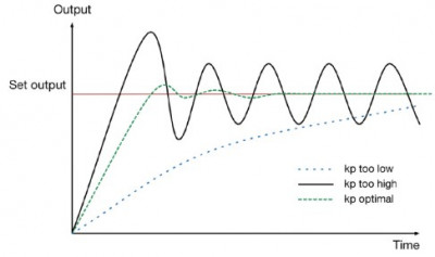
kp value, the system will behave similarly to a simple on/off temperature controller, causing the actual temperature to oscillate around the set temperature. The figure below illustrates how different values of
kp affect the behavior of an idealized system.

Here, it can be observed that if the value of
kp is too low, the temperature may never reach the desired level, or it may take too long to do so. On the other hand, if the value of
kp is too high, oscillations will occur at the output, and their magnitude will not decrease. The appropriate value of
kp will quickly adjust the output to the desired level, perhaps with a slight overshoot, and then the oscillations will quickly settle to an acceptably low level.
Finding the suitable value of
kp is referred to as system tuning. Tuning of PID control will be discussed further.
Returning to the example with a set temperature of 30°C but an actual temperature of 25°C, in this case, it is still desirable for the heater to dissipate the maximum power, i.e., a PWM duty cycle of 255 (100%). If a value of 50 is chosen for
kp, then a discrepancy of 5 units will lead to the following output power:
Output = Discrepancy x
kp = 5 x 50 = 250
Once the system is only 1°C away from the set temperature, the output power will decrease to the following value:
Output = Discrepancy x
kp = 1 x 50 = 50
This power may be sufficient or insufficient for the system to reach the desired temperature. Systems vary, so the controller requires tuning.
Integral (I)
If achieving the required precision of power control through proportional control is not possible, calculations may require the addition of a value
I to calculate the output power using the following formula:
Output = Discrepancy x
kp + I x
ki.
Here, a new constant
ki is introduced, scaling our new mysterious property called "I" (let's reveal the secret - it's precisely Integral), and the output power is calculated by adding this integral component to the previously discussed proportional component. This type of controller is called a PI controller (PI, or sometimes P + I, don't confuse it with "Pi" in Raspberry Pi). Both the use of a purely proportional controller and a PI controller sometimes yield quite acceptable results, eliminating the need to add the third component of the PID controller, D.
The integral component is calculated by maintaining the current sum of discrepancies with each temperature measurement. When the discrepancy is positive (heating), the I-component will continue to increase, exceeding the value of the initial response. Reduction will only start when the discrepancy becomes negative after exceeding the set temperature.
Once the actual temperature reaches the set temperature, the I-component has a calming effect, smoothing out temperature changes to better maintain the temperature at the desired value.
The only problem with the I-component is that it provides a large boost as the temperature rises, potentially leading to a significant temperature overshoot, after which time is required for it to decrease to the set temperature and stabilize.
Derivative (D)
In practice, the D-component is often not used in real control systems because the benefits of using it to reduce overshoots are outweighed by the complexity of tuning.
When adding the D-component to the control program to counteract overshoot effects, the output power is calculated using the following formula:
Output = Discrepancy x
kp + I x
ki + D x
kd.
The D-component measures how quickly the discrepancy changes between each temperature measurement, and therefore, it somewhat predicts where the temperature is heading.
PID Controller Tuning
Tuning a PID controller involves finding values for
kp,
ki, and
kd that make the system behave appropriately. I recommend simplifying things and using only PI control, setting
kd to zero. Then, you only need to tune two parameters. In fact, this simplification eases the tuning process for most systems, although it slightly increases the time spent on tuning.
In the section "Experiment: Thermostatic PID Controller," I will guide you through a trial-and-error method that works well for the temperatures the controller deals with. The rest of the section will focus on the most popular method of PID tuning known as the Ziegler-Nichols method. This method significantly streamlines the process of obtaining values for
kp,
ki, and
kd, reducing it to a series of experiments followed by straightforward calculations.
Ziegler-Nichols tuning starts with setting
ki and
kd to zero in order for the controller to work in proportional mode. Then, the
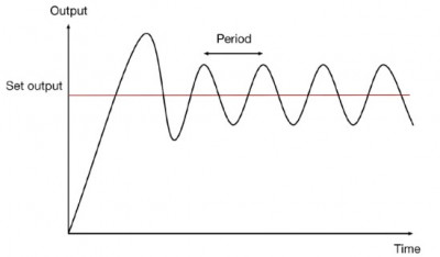
kp value is gradually increased until the output power starts to oscillate. The
kp value at which this happens is called
ku.
After determining the value of
ku, you need to measure the number of oscillations per second (oscillation period, referred to as
pu).

To obtain it, you should plot the power readings on the load, as was done in the experiment in the section "Experiment: How Good Is a Thermostat Based on On/Off Control?"
Then, you can calculate the values for
kp,
ki, and
kd:
kp = 0.6 x ku
ki = (2 x ku) / pu
kd = (ku x pu) / 8
If you are using a PI controller, it is better to use the following calculations:
ku = 0.45 x ku
ki = (1.2 x kp) / pu
kd = 0
You can find an article on the Ziegler-Nichols method in Wikipedia (
http://en.wikipedia.org/wiki/PID_controller).