Experiment: Controlling RGB LEDs with Arduino and Raspberry Pi
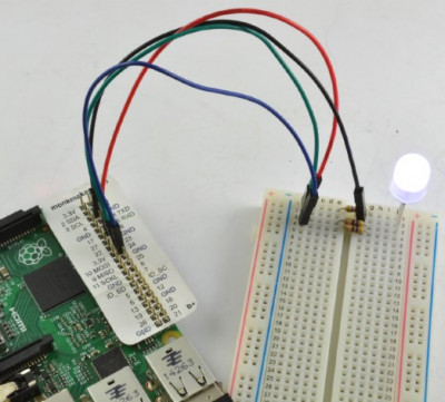
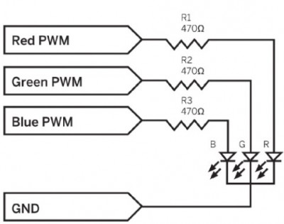
In this experiment, we will control the color of an RGB LED using both Arduino and Raspberry Pi. In the version of the experiment performed on Raspberry Pi, we will use a graphical user interface with three sliders to control the color. The images below depict the Raspberry Pi setup and the experiment's schematic.

-
image.png (255.21 KiB)
Connecting a breadboard for mixing colors using aspberry Pi Viewed 28548 times

-
image.png (66.25 KiB)
The scheme of the experiment with an RGB LED Viewed 28548 times
Components
For this experiment, you will need the following components for both Arduino and Raspberry Pi:
LED1 - RGB LED
R1-3 - 470 Ohm 0.25W resistors
400-point breadboard
Male-to-Male jumper wires
Male-to-Female jumper wires (only for Raspberry Pi)
Please note that Male-to-Female jumper wires are only needed for connecting to the GPIO pins on Raspberry Pi (if you plan to conduct this experiment with Raspberry Pi as well).
To achieve optimal brightness and the best color balance, careful selection of resistors with matching resistances is essential. However, it's easier to obtain the components if you use 470 Ohm resistors for all three channels. They will work with both Raspberry Pi and Arduino.
By the way, the brightness and efficiency of RGB LEDs are such that even at a current of only 3 mA (6 mA for Arduino), the LED will shine quite brightly.
Connection to Arduino
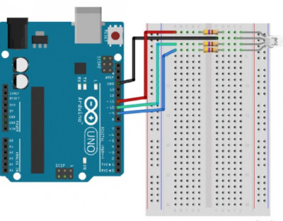
In the Arduino version of this experiment, we use the serial monitor interface to set the proportions of red, green, and blue colors. The diagram below shows the layout of the breadboard and how to connect it to Arduino.

-
image.png (169.76 KiB)
Layout of a breadboard for mixing RGB LED colors using Arduino Viewed 28548 times
The longest lead of the RGB LED is the common cathode, which should be connected to the GND socket on the Arduino board. The order of connecting the other pins may not be the same as shown here, so you may need to rearrange some wires if your colors mix incorrectly.
Arduino Code
The sketch sets up three PWM channels to control the brightness of each of the three colors.
Code: Select all
const int redPin = 11;
const int greenPin = 10;
const int bluePin = 9;

void setup() {
  pinMode(redPin, OUTPUT);
  pinMode(greenPin, OUTPUT);
  pinMode(bluePin, OUTPUT);
  Serial.begin(9600);
  Serial.println("Enter R G B (E.g., 255 100 200)");
}

void loop() {
  if (Serial.available()) {
    int red = Serial.parseInt();
    int green = Serial.parseInt();
    int blue = Serial.parseInt();
    analogWrite(redPin, red);
    analogWrite(greenPin, green);
    analogWrite(bluePin, blue);
  }
}
Let's clarify some aspects of the sketch using comments:
1. Each of the three PWM values, which should be in the range of 0 to 255, is read into variables.
2. Then, PWM output is set for each channel.
Uploading and Running the Program
After uploading the sketch, open the Serial Monitor window in the Arduino IDE. Then, enter three numbers, each in the range of 0 to 255, separated by spaces, and press the "Send" button. The LED should change color to match the values of red, green, and blue you just entered.
You can individually test each of the channels by entering 255 0 0 (red), 0 255 0 (green), and 0 0 255 (blue).