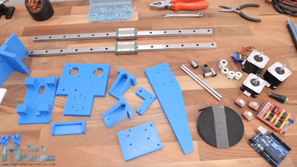
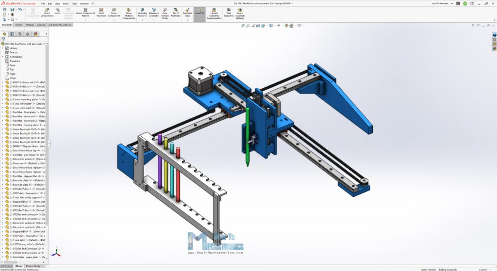
Here are all the parts needed for assembling the pen plotter.

Here’s a list of components needed for assembling this DIY CNC machine. The list for the electronics components can be found below in the circuit diagram section of the article.
- Bolts and Nuts set + Flat Head Screws 3x16mm
All right, so now we can start assembling the machine. I started by securing the base plate and the bracket for the linear rail together with the help of some M3 bolts. All of the bolts for assembling this machine are actually M3 with various lengths except for few M5 bolts needed for GT2 pulleys.

Once we have the two sides ready, we can secure the X-axis linear rail to them with two bolts on each side. These MGN15H rails provide very smooth and play free motion, as their sliding blocks have balls or rollers inside them.

However, before installing them, it’s a good idea to clean and grease them well in order to work properly.
Next, the Y-axis rail should go on top of the X-axis sliding block and for securing them together we will use a central mounting plate. First, we can install the Y-axis rail to the central plate using three bolts.

Then we can install the two NEMA 17 stepper motors. One goes on the top side and the other at the bottom side of the plate. As I mentioned earlier, we need some M5 bolts and nuts for installing the GT2 pulleys in place. The two pulleys here are actually idler pulleys which are used for providing grip for the X-axis GT2 belt and the toothed pulley which goes on the stepper motor.

As for installing that pulley, we should measure and level it according to the idler pulleys. As for the Y-axis, we only need one idler pulley which goes on the other side of the rail, as the belt for this axis will be installed in a loop.

Ok, next is the marriage or connecting the two axes together. We simply do that by securing the central plate to the X-axis sliding block using four M3 bolts. With this the machine got its main shape and now the Y-axis sliding block can reach any position in the work area.

We can continue now with assembling the pen lifter mechanism. This mechanism is composed of two parts, one fixed that’s bolted to the Y-axis sliding block, and the other one that will be sliding up and down. Once the fixed part is secured in place, we can install the Z-axis stepper motor on it. This stepper is also a NEMA 17 but it’s shorter, 23mm instead of 40mm, in order to cut on weight.

Then we can install the lifter which is simply attached to the shaft of the stepper. The grub screw that I had was a bit long for it, so I put lifter to the shaft without it, but its hole has a shape as the shaft so the motion will be transferred well. I actually ended up modifying this part a little but, no worries you will get the updated version of it in the download files.
Next, I inserted the four linear bearings into the sliding part and secured the micro servo in place. Then I also secured the pen holder part right next to the servo.

For connecting the fixed and the sliding parts together, first we need to pass the servo wire through a hole in the fixed part and then insert the 6mm rods from the top, through the bearings and the fixed part hole. While installing this rod, we should also insert a spring in-between the fixed and the sliding part in a way that it pushes the sliding part down.

This will help the pen to have a better contact with the work surface. At the bottom side of the fixed part, there are opening where we can insert M3 nuts and use them for securing the 6mm rods in place.
Next, we can assemble the pens holder unit that goes on one side of the machine. It’s composed of top and a bottom part with openings to accommodate up to 12 pens.

I continued with installing the belts. First, we need to measure how much length we need and cut it approximately to size. For attaching the belt to the sliding block, I made these cool belt connectors, where the belt goes around a hollow shaft and in between two walls that doesn’t allow the belt to move.

Using a M3 bolt we can secure the first connector on one side of the block, and repeat the same procedure for the other side. We can move the connectors along these slots here and so tension the belt as much as we want.

As for the X-axis, the belt will go in a straight line from one to the other side, while passing through the pulleys in a way that will provide tension or grip with the stepper motor pulley.

For tensioning the X-axis belt, I made these connectors that have a shape as the belt and so we can tight them to the sides of the machine.

Next, we can install the limit switches.

I actually ended up lowering a bit this Z-axis limit switch, and as for the X and Y limit switches I used the ones from my previous project which already had wires connected to them.


