Page 1 of 1

Motors, pumps and actuators

Posted: 05 Oct 2023, 05:48
by Oleg
Experiment: Understanding DC Motors

In a previous experiment, we've already worked with a DC motor. The fundamental principles we'll learn while dealing with DC motors are applicable to many other mechanisms you might want to control with Arduino or Raspberry Pi. Electro-motors, in particular, enable various useful output devices, including pumps and linear actuators, which we'll become acquainted with.

In the image below, you can see a selection of various sizes and shapes of DC motors.
Varieties of DC motors
image.png (69.36 KiB)
Varieties of DC motors Viewed 4930 times
As we learned from the "Experiment: Controlling a DC Motor," you can't directly control a DC motor with the contacts of Arduino or Raspberry Pi because it requires a relatively high current. Therefore, we used a transistor to enable us to turn the motor on and off. Now, our goal is to learn how to control its rotation speed.

HOW DO DC MOTORS WORK?

Typically, a DC motor consists of three main parts, as shown in the illustration: the external (stationary) part of the motor is the stationary magnet (stator), and on the shaft inside the stator is the moving part of the motor, composed of the rotor and the commutator.

The rotor carries wire coils (windings). In the illustration, you can see three such coils wound around three shaped segments of the rotor, connected to the commutator. The purpose of the commutator is to sequentially excite the magnetic field in the coils as the rotor rotates, ensuring that the next coil is always attracted to the stator's permanent magnets, thus causing the rotor to spin.

The commutator is a segmented ring (three segments are shown in the illustration), and brushes are used to connect the power contacts to individual segments of the commutator as it rotates together with the rotor.
Internal structure of a DC motor
image.png (109.38 KiB)
Internal structure of a DC motor Viewed 4930 times
The model of a DC motor with three sets of windings described here is quite typical for such small DC motors, as shown in the image at the beginning. A valuable property of DC motors is that changing the polarity of the voltage on the contacts makes the motor rotate in the opposite direction.

DC motor speed controlors

Posted: 05 Oct 2023, 05:52
by Oleg
Equipment

In this experiment, the same equipment is used as in the "Experiment: Controlling a DC Motor" section (viewtopic.php?p=14#p14). However, here you won't just turn the motor on and off; you'll also control its speed.

If you haven't done so already, assemble the circuit from the "Experiment: Controlling a DC Motor" section (viewtopic.php?p=14#p14). As a reminder, the layout of the prototype board for this experiment is shown in the image below.
Layout of breadboard for motor experiments
image.png (131.13 KiB)
Layout of breadboard for motor experiments Viewed 4929 times
Connecting Arduino

Connect the prototype board to Arduino as shown in the figure below: connect the ground from the prototype board to the GND socket and the control output from the prototype board to the D9 socket.
Connecting breadboard to Arduino
image.png (210.86 KiB)
Connecting breadboard to Arduino Viewed 4929 times
Arduino Program

The Arduino sketch for this experiment:

To input the duty cycle and set the desired motor rotation speed, we'll use the Serial Monitor in Arduino IDE:

Code: Select all

const int controlPin = 9;

void setup() {                    // (1)
  pinMode(controlPin, OUTPUT);
  Serial.begin(9600);
  Serial.println("Enter Duty Cycle (0 to 100)");
}

void loop() {                     // (2)
  if (Serial.available()) {       // (3)
    int duty = Serial.parseInt();
    if (duty < 0 || duty > 100) {  // (4)
      Serial.println("0 to 100");
    }
    else {
      int pwm = duty * 255 / 100;
      analogWrite(controlPin, pwm);
      Serial.print("duty set to ");
      Serial.println(duty);
    }
  }
}
Let's clarify some aspects of the sketch using comments:
1. The setup function sets controlPin as an output and initializes the serial communication through USB with Serial.begin. This allows you to send duty cycle values from your computer to Arduino.
2. The loop() function checks if there is any data available in the serial input using Serial.available().
3. If there is data, which should be a number, it is read from the character stream and converted to an int using parseInt().
4. We check if the received value is in the range of 0 to 100. If it's not, a message is sent to the Serial Monitor reminding you of the valid range. If the number is within this range, it is converted to a value between 0 and 255, and then analogWrite() is used to set the PWM value. This conversion is necessary because the analogWrite() function of Arduino expects a PWM value in the range of 0 to 255, where 0 corresponds to 0% and 255 corresponds to 100%.

Text and Numbers

We will often read numbers through the Serial Monitor, so it's essential to understand what the parseInt function does and how information is sent to Arduino via USB.

As mentioned earlier, one way to interact with Arduino (and, for that matter, with Raspberry Pi) is through the serial interface. Arduino Uno has a built-in serial interface connected to digital pins D0 and D1. These pins should not be used for regular input/output because they provide a serial interface between your computer and Arduino via a USB interface chip that converts USB serial output into direct serial input that Arduino understands.

When you input a message into the Serial Monitor and send it to Arduino, the text of the message is converted into a stream of bits (high and low signals), which are then grouped into eight-bit chunks (bytes) at the destination. Each of these bytes corresponds to a specific Latin alphabet letter or a numerical code in ASCII (American Standard Code for Information Interchange).

When the running Arduino program receives a message in the form of such a sequence, it can either read one byte (character) at a time or use the parseInt function, which reads characters and, if it turns out that the character is a digit, constructs a number from those digits. For example, the number 154 would be sent as three characters: 1, 5, and 4. If a newline character, space, or a non-digit character follows after the number, the parseInt function recognizes that all the digits from the transmitted number have been received and returns the value 154 as an int. Moreover, even if there's a slight delay after sending the last digit, it's sufficient for parseInt to detect the end of the number.

Uploading and Running the Program

Upload the program to Arduino. On the computer where you're programming Arduino, open the Serial Monitor in Arduino IDE. To do this, click on the magnifying glass icon in the upper right corner of the Arduino IDE window (circled in the image below).

Next, you'll be prompted to enter a duty cycle value from 0 to 100. Try entering different values and see how it affects the speed of the DC motor. When you decide to stop the motor, simply set the duty cycle to zero.

Note: If you go down to values like 10-20, the motor may not rotate but emit a buzzing sound since there won't be enough energy to overcome friction and initiate rotation.
Using the serial interface monitor
image.png (112.12 KiB)
Using the serial interface monitor Viewed 4929 times

Controlling DC motors with relays

Posted: 05 Oct 2023, 06:00
by Oleg
Using Relays with Arduino or Raspberry Pi

If you intend to intermittently turn a motor on and off using Arduino or Raspberry Pi, you can employ relays. While this approach may be considered somewhat old-fashioned, it has several advantages:

- It is straightforward to implement and requires minimal components.
- It provides excellent isolation between the high-current motor, which generates a lot of noise, and the delicate construction of the Pi and Arduino.
- It enables you to work with high currents (when the relay is selected correctly).
- Ready-made relay modules are available that can be used directly with Raspberry Pi or Arduino.

However, there are some drawbacks to working with relay modules:

- They are relatively bulky.
- They can only turn the motor on or off, not control its speed.
- Since relays are electromechanical devices, they typically endure no more than 10 million switching operations before something breaks.

Electromechanical Relays

The image below displays perhaps the most common type of relay, often referred to as a "sugar cube" relay due to its shape, though typically these relays are black, not the color of actual sugar cubes.

When a current (typically around 50 mA) flows through the relay coil, it acts as an electromagnet and attracts two contacts towards each other, creating a connection between them. These contacts are designed to handle high voltage and current, capable of switching tens of amperes.
Relay
image.png (47.02 KiB)
Relay Viewed 4927 times
Although we'll use relays to control a DC motor, the relay itself functions as a simple switch, allowing you to control almost anything with it.

These types of relays are called "single-pole changeover" relays (abbreviated as SPCO), as they have not just two contacts that can be either closed or open, but three: the common contact (usually labeled COM) and two other contacts: normally open (NO) and normally closed (NC). In this context, "normally" means "without power applied to the relay coil." Therefore, NO and COM contacts will be open (not connected) until the relay coil is energized. The normally closed contact operates in the opposite manner, where the NC and COM contacts are closed by default but will disconnect when the relay coil is energized.

In standard situations, only two relay contacts—NO and COM—are used to control the connected device.

Using Relays with Arduino or Raspberry Pi

When using relays with Raspberry Pi or Arduino, you will need relays designed for a 5V coil voltage. Relay coils consume too much current (around 50 mA) to be controlled directly by Raspberry Pi or Arduino, so in both cases, you'll need to include a small transistor in the circuit to manage the relay coil at 5V.
Using a small transistor to switch relays
image.png (72.36 KiB)
Using a small transistor to switch relays Viewed 4927 times
As mentioned, the relay coil is designed to operate at 5V and requires approximately 50 mA of current, which is too much for Arduino and excessive for a Raspberry Pi GPIO pin. Therefore, similar to what we did in the "Experiment: Controlling a DC Motor" section, we'll use a transistor to control the relay coil, with the relay coil acting as the "load" instead of the motor.

This setup is practical only when the motor (or any other load you want to control) consumes a significant amount of current, making it unsuitable for direct control using just a transistor.

Like the motor, when relays are switched on and off, they can produce voltage spikes, so it's necessary to include a diode in the circuit.

It's evident that in the circuit shown above, the switching part of the relay is electrically isolated from the part with the coil. This reduces the likelihood of electrical interference, voltage spikes, and other harmful electrical phenomena reaching your Arduino or Raspberry Pi.

Since a relay powered by a 5V coil requires only about 50 mA of current, a budget transistor like 2N3904 will suffice in our case.

Relay Modules

If you have multiple devices you want to control, and they adhere to the previously mentioned limitation of relay-based control (typically limited to on/off switching), it would be convenient to acquire a relay module, like the one shown in Fig. 7.9.
8-channel relay module
image.png (166.67 KiB)
8-channel relay module Viewed 4927 times
These modules are inexpensive and can be readily purchased on online marketplaces like AliExpress. They typically come with the relays themselves, transistors to control them, and small LEDs to help identify which specific relay is activated. Given their setup, such relay modules can be connected directly to Raspberry Pi or Arduino.

Relay modules may contain varying numbers of relays, from a single relay to eight or more. Usually, relay modules have the following contacts:

- GND - Ground.
- VCC or 5V - Connect this contact to the 5V pin on Raspberry Pi or Arduino; when you activate it, it can supply voltage to the relay coils.
- Data pins - Each data pin controls one of the relays. Sometimes these pins may be active high, meaning they activate the relay when transitioning to a high state. In other cases, the data pin may be active low, activating the relay when the GPIO pin goes low.

Additionally, relay modules feature screw terminals connected directly to the working relay contacts that close the power circuits of the controlled devices.

Experiment: DC motor control with a relay module

Posted: 05 Oct 2023, 06:03
by Oleg
Using Relays to Control a DC Motor

In this experiment, we will simply turn a DC motor on and off using relays.

A ready-made relay module with eight relays is used here, but for our experiment, we will need just one relay. So, if you prefer, you can use a module with fewer relays.

Components

For this experiment with Arduino and Raspberry Pi, you will need the following components:
- Small direct current (DC) motor with a 6V power supply
- Relay module
- 4xAA battery holder (6V)
- Jumper wires compatible with the relay module

Some relay modules connect to Arduino or Raspberry Pi using connectors, while others use pins, so choose appropriate jumper wires. This means that to connect the relay module to Arduino using pins, you will need "male-to-female" jumper wires, and for connecting it to Raspberry Pi, you will need "female-to-female" jumper wires.

Experiment Setup

The experiment setup is illustrated in the diagram below. The relay contacts act as switches, each of which can be in one of two positions. As mentioned earlier, there are common, normally open (NO), and normally closed (NC) contacts. When the relay coil is not energized, the common contact is connected to the normally closed contact. When power is supplied to the coil, the switch's position changes, and the common contact connects to the normally open contact.
Circuit for controlling a DC motor with a relay module
image.png (54.45 KiB)
Circuit for controlling a DC motor with a relay module Viewed 4927 times
The programs for this experiment on Arduino and Raspberry Pi are almost identical to those we used in the "Experiment: Controlling a DC Motor" section. The only difference arises if your module has an active-low logic, like the one I worked with.

Arduino Program

The program will turn on the relay (and thus the DC motor) for 5 seconds, then turn it off for 2 seconds, and this operation will repeat:

Code: Select all

const int controlPin = 9;

void setup() { 
  pinMode(controlPin, OUTPUT);
}

void loop() { 
  digitalWrite(controlPin, LOW);   // (1)
  delay(5000);
  digitalWrite(controlPin, HIGH);
  delay(2000);
}

In the line marked with comment 1, the code is exactly the same as in the "Experiment: Controlling an LED" section, except that the values `LOW` and `HIGH` in the `digitalWrite` functions are swapped. If you find that the motor turns on for 2 seconds and off for 5 seconds when you run the program, it means that your relay module's logic is active high, and you should leave the values `LOW` and `HIGH` in the order they were in the "Experiment: Controlling an LED" section.

Remember to handle the power supply and connections with care to ensure safe experimentation.

Engine selection

Posted: 05 Oct 2023, 06:25
by Oleg
DC Motors: Torque, Speed, and Gear Reduction

Direct current (DC) motors come in various shapes and sizes, and it's essential to choose one with sufficient power for your project. When dealing with a DC motor, you should understand two primary characteristics: the force of rotation it can generate (torque) and how fast it rotates.

If it rotates faster than needed but lacks sufficient torque, you can compensate for this deficiency by using a gearbox.

Torque

In simple terms, torque refers to the rotational force of a motor. The greater the torque of a motor, the more force it can exert to rotate its shaft (rotor).

From a scientific perspective, torque is defined as the force multiplied by the distance, where the force is measured in newtons (N), and the distance is measured in meters (m). In a more practical context, the force component of torque is often expressed as the force required to lift a specific weight in kilograms (or ounces) over a distance measured in centimeters (or inches).

Distance is included in the equation because, as the distance from the rotor's axis increases, the motor can apply less and less force to the load. For example, if the torque of a motor is stated as 1 kgf/cm (kilogram-force per centimeter), it means that at a distance of 1 cm from the rotor's axis, the motor can hold a weight of 1 kg, i.e., it won't be able to handle a more substantial weight. However, at a distance of 10 centimeters from the rotor's axis, it can only hold a weight of 100 grams (10 cm x 100 g = 1 kgf/cm). The relationship between weight and distance from the motor's axis is illustrated in the figure below:

1 cm
The essence of torque
image.png (46.35 KiB)
The essence of torque Viewed 4927 times
Rotational Speed

DC motors rotate at a relatively high speed, which is why they are often used in conjunction with transmissions or as geared DC motors. A typical low-voltage DC motor can rotate at speeds of 10,000 revolutions per minute (RPM) or approximately 166 revolutions per second.

Gear Reduction

Although you can slow down the motor's speed effectively using pulse-width modulation (PWM), reducing the energy supplied to the motor also reduces the generated torque. Gear reduction is a way to slow down the rotation of motors while increasing the torque as a side effect. For example, if you use a 5:1 gearbox (as shown below) with 50 teeth on one gear and 10 teeth on the other, for every five rotations of the motor, only one rotation is transferred from the gearbox. However, the torque at the output of the gearbox will be ten times stronger than what you would get directly from the motor.
Transmissions
image.png (102.52 KiB)
Transmissions Viewed 4927 times
Geared DC Motors

Because motors are so frequently used with gearboxes, it's often better to purchase a geared DC motor where the gearbox is already combined with the electric motor.

The most budget-friendly geared DC motors come with plastic gears. They work but may not last as long or provide as much torque as geared DC motors with metal gears.

Pumps

Typically, pumps are constructed based on regular direct current (DC) motors or, occasionally, brushless DC motors (which will be discussed later). A pump provides energy to a mechanism that transfers liquid from one reservoir to another.

Enthusiasts often use two common types of pumps: hose pumps or dynamic pumps.
Hose pump (left) and dynamic pump (right)
image.png (133.65 KiB)
Hose pump (left) and dynamic pump (right) Viewed 4927 times
Both types of pumps are driven by direct current motors, but their properties differ significantly. If you require a slow, steady flow, opt for a hose pump, while a dynamic pump is suitable for rapid and turbulent flows.

Hose Pumps

Hose pumps are designed for very controlled liquid transfer. They are frequently used in medicine and research to pump precisely defined volumes of liquid. For more precise flow control, hose motors are sometimes controlled by stepper motors.

The principle of a hose pump is illustrated in the figure below. The pump consists of a motor and a gearbox that rotates a shaft with rollers, compressing a flexible tube and pushing liquid through it. Not surprisingly, the tube wears out over time due to continuous compression, so it needs to be replaced. Therefore, the tubes in such pumps are typically replaceable.
Working principle of the hose pump
image.png (81.94 KiB)
Working principle of the hose pump Viewed 4927 times
By supplying energy to the gearbox of a hose pump using PWM and an H-bridge, you can control not only the speed but also the direction of the liquid flow.

Hose pumps are self-priming, meaning that if they are positioned slightly above the liquid level, they generate enough suction to draw in some liquid and start pumping it.

VOLUME FLOW RATE

Volume flow rate is the amount of liquid a pump can transfer in a given unit of time. Various units are used to measure this volume and time. The volume flow rate of a small hose pump may be 50 ml/min (milliliters per minute), while a dynamic pump designed for garden irrigation may have a volume flow rate of 5 l/min (liters per minute).

Dynamic Pumps

If you aim to quickly transfer a large volume of liquid, you will need a dynamic pump. There are many types of dynamic pumps, but one of the most common is the centrifugal pump.
Operating principle of the centrifugal dynamic pump
image.png (70.21 KiB)
Operating principle of the centrifugal dynamic pump Viewed 4927 times
Liquid enters the pump from the front along the motor's axis, where the blades rotate. These blades impart centrifugal force to the incoming liquid, pushing it towards the edge of the pump casing and outward.

Dynamic pumps are not self-priming, and they require liquid at their inlet before pumping. Unlike hose pumps, dynamic pumps can pass liquid through them even when they are not actively pumping it. Some pumps of this type are designed for garden ponds or aquariums and can be completely submerged underwater. Another difference between dynamic pumps and hose pumps is that dynamic pumps cannot pump liquid in reverse.

In some dynamic pumps, brushless motors are used, and they come with their built-in electronic control in the motor casing. This design allows for maximum liquid pumping power in a compact pump.

Linear actuators

Posted: 05 Oct 2023, 06:32
by Oleg
Linear actuators transform the rotation of a direct current motor into linear motion. Such devices are often used for remotely opening and closing windows and doors.

In linear actuators, the key component is a threaded drive rod onto which a peculiar nut is threaded. This nut cannot rotate but freely moves up and down the rod when it rotates, thus moving the working part of the actuator (shaft) forward and backward. The figure below illustrates how this works.
Operating principle of the linear actuator
image.png (59.54 KiB)
Operating principle of the linear actuator Viewed 4927 times
Linear actuators move the shaft relatively slowly because the threaded rod and nut effectively act as a gearbox, and a standard gearbox is usually installed on the motor's side. Due to the low speed but the considerable power of a direct current motor, a linear actuator typically provides strong thrust or push. The mechanism shown in the figure generates a force of 1500 N (newtons), equivalent to lifting a load of 150 kg. Under full load, a similar linear actuator's motor can draw 5 A of current at 12 V.
Linear actuator
image.png (132.23 KiB)
Linear actuator Viewed 4927 times
Typically, the motor of a linear actuator receives power through an H-bridge with a maximum current capacity of at least 5 A, enabling it to rotate in both directions. To prevent damage to the linear actuator when the nut reaches one end of the threaded rod, such devices are usually equipped with limit switches that automatically cut off power as soon as the nut hits one end. This simplifies motor control since you can set the H-bridge to power the motor in either direction for a limited time, allowing the mechanism to travel the entire distance backward or forward.

Solenoids

Posted: 05 Oct 2023, 06:34
by Oleg
Solenoids are often used in conjunction with door latches and simple water valves. Similar to linear actuators, they provide linear motion for the rod (plunger) inside them, but a solenoid is a much simpler device. In fact, it's an electromagnet that facilitates the linear motion of the rod. The path it travels inside the solenoid is usually very short, mere centimeters.

Under the influence of an electric current, the solenoid coil is energized, and magnetic forces push the rod, overcoming spring compression. When power to the coil is cut off, the rod freely returns to its initial position due to the spring's action. The principle of how a solenoid works is illustrated in the figure below.
Operating principle of the solenoid
image.png (52.04 KiB)
Operating principle of the solenoid Viewed 4926 times
A solenoid-based regulating water valve, as shown in the figure below, is designed to switch the flow of pressurized tap water. When there is no power supplied to the valve, water does not flow through it. However, when the coil is energized, the plunger moves backward, allowing water to flow freely through the valve as long as it is powered.
12-volt control water valve
image.png (161.95 KiB)
12-volt control water valve Viewed 4926 times
This 12-volt device is commonly used in household washing machines. Models of such valves designed to work with alternating current at 120 V or 220 V can also be found and are used in household applications. Working with higher voltage in contact with water can be dangerous, so I strongly recommend using 12-volt pumps and valves for your projects.

Project: home irrigation system

Posted: 25 Jul 2024, 22:59
by robotwf
In this simple Arduino project, a specified volume of water is supplied daily to indoor plants using a hose pump.
Image

The timer, which would allow setting when to water the plants, is not used here. Instead, the device measures the intensity of daylight, and watering occurs as soon as it starts to darken.

Project scheme

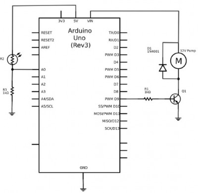
The schematic diagram of this project is shown in the figure below. The MР8А14 transistor is used by Arduino to turn the pump motor on and off. The diode DI provides protection against negative voltage spikes.

In the left part of the diagram, we see a photoresistor and a fixed resistor that form a voltage divider for measuring light intensity on the A0 analog pin of the Arduino board. The more light hits the photoresistor, the lower its resistance, so the voltage at pin A0 increases up to 5V.

Assembling such a project is very simple. It is unlikely that wires will already be attached to the motor of your pump to the output contacts, so all the soldering that needs to be done here will involve soldering the corresponding mounting wires to the pump motor.
Image

Components

In this Arduino project, you will need the following components:

Arduino Uno
Q1 - Composite transistor MР8А14 R1, R3 - 1 kOhm resistor
R2 - 1 kOhm photoresistor
D1 - 1N4001 diode
Hose pump 12V
400-point solderless breadboard
Jumper wires "male to male" (for Arduino only)
Tube for insertion into the pump, 1m
Power supply 12V 1A
Large water container
Mounting wires, soldered to the pump motor

A variety of hose pump used in this project is designed for aquarium use and can be purchased for a very small amount of money.

The tube I used here came with a watering kit I bought at a hardware store. Along with it, I also acquired small plastic connecting sleeves, which are used to connect sections of the tube together. The connections of the tubes must be sealed, otherwise the pump will not work.

Project Assembly

To assemble this project, you will need to work a bit with the breadboard and securely attach the water container manually.

Step 1. Solder wires to the motor
Solder mounting wires to the pump motor contacts, if they are not already there. The wires should be long enough to reach from the pump to the breadboard and Arduino. Half-meter wires will be sufficient.
Step 2. Assemble the breadboard
Place the project components on the breadboard as shown in the diagram. Make sure the transistor and diode are installed correctly.
Image

Step 3. Attach the tube to the pump
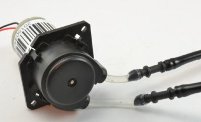
You will need two pieces of tubing. One should submerge into the water container to its full depth, reaching from the pump mounting hole located at the top of the container to the bottom. The second one should run from the pump's outlet hole to the plant you intend to water. The pump and tubes are shown in close-up in the image.

The input and output of the pump are usually not marked, but hose pumps can move liquid in both directions. Therefore, if you notice that the pump is sucking in water instead of pumping it, it is better to resolder the mounting wires on the motor rather than rearranging the tubes.
Image

I decided that it would be convenient to insert the pump into the water container from the top and glue the motor to the pump. The input tube then goes straight into the container, while the output tube protrudes from the side and is directed towards the plant. To insert the pump, I had to trim the neck of the milk bottle I used a bit.
The image shows the design I ended up with, but you can certainly install the pump at the bottom, next to the breadboard. However, in that case, you will need a longer tube.
Image

Program

The Sketch with which I calibrated the light sensor:

Code: Select all

const int lightPin = A0;

void setup() {
  Serial.begin(9600);
}

void loop() {
  int lightReading = analogRead(lightPin);
  Serial.println(lightReading);
  delay(500);
}
Arduino Sketch for this project:

Code: Select all

const int motorPin = 9;   // (1)
const int lightPin = A0;

const long onTime = 10 * 1000; // 60 seconds  (2)
const int dayThreshold = 200;              // (3)
const int nightThreshold = 70;

boolean isDay = true;                      // (4)

void setup() {
  pinMode(motorPin, OUTPUT);
}

void loop() {        // (5)
  int lightReading = analogRead(lightPin);
  if (isDay && lightReading < nightThreshold) { // it went dark (6)
    pump();
    isDay = false;
  }
  if (!isDay && lightReading > dayThreshold) {   // (7)
    isDay = true;
  }
}

void pump() {   // (8)
  digitalWrite(motorPin, HIGH);
  delay(onTime);
  digitalWrite(motorPin, LOW);
}
Let's clarify some points in the sketch using the line markings provided in the comments:

1. The sketch starts by defining constants for the two Arduino pins used: the pin for controlling the motor and the analog input pin (lightPin) where a photoresistor is used to measure light intensity.

2. The constant onTime specifies how long the pump should remain on each night. When testing the project, a brief period, such as 10 seconds, can be set here to avoid long waiting times.

The most interesting part of the sketch is where we determine that it has become dark outside. Since the Arduino board does not have built-in clocks, it cannot determine the time unless an RTC (real-time clock) is added to the project. In this project, I plan to water the plant once a day, so the onset of dusk is the most suitable factor for triggering the pump. After watering, you do not intend to water the plant until the next dusk, i.e., until the day ends.

3. To make it easier to distinguish between night and day, two constants, dayThreshold and nightThreshold, are defined. These values may need to be adjusted depending on the placement of the plant pot and the sensitivity of your photoresistor. The fundamental idea is this: if the current light value is above dayThreshold, it is daytime, and if it is below nightThreshold, it is nighttime. You may wonder why there are two constants instead of just one. The reason is that during dusk, when it is just starting to get dark, the light level may fluctuate around the threshold value for some time, causing the device to trigger multiple times.

4. The boolean variable isDay holds the answer to whether it is currently day or not. If isDay is true, then from the watering setup's perspective, it is daytime.

5. The logic for determining whether it is time to water the plants is encapsulated in the loop function. It takes the light intensity value as an input.

6. If it is currently day but the light intensity value is below nightThreshold, it indicates that dusk has just fallen - triggering the watering function. Subsequently, the isDay variable is set to false, signifying that night has arrived, and watering should be stopped for now.

7. The second if statement in the loop checks if it is currently night (isDay) and if the light intensity value does not exceed the dayThreshold. If both conditions are met, isDayis set to true.

8. Finally, the pumpfunction turns on the pump, waits for the period specified in onTime, and then turns off the pump.

Download and run the program

Before starting the main part of the project, it is necessary to upload a test program to the Arduino - this will help to adjust suitable values for dayThreshold and nightThreshold. So, upload this sketch to the Arduino and open the serial monitor.

A series of values corresponding to the current light intensity should appear on the serial monitor every half a second. Note the light intensity value during a very cloudy day. Approximately half of this value should match the dayThreshold- this way, our device will work correctly even on the cloudiest days.

Next, wait for dusk near the plant pot, and again take readings. You can try to guess or simply cover the light sensor with your finger.

Double the obtained value and set the result as the nightThreshold. Note: nightThresholdshould be significantly lower than dayThreshold. Some compromises may be needed when evaluating these two values.

Now you can adjust the values of dayThresholdand nightThresholdin the actual sketch and upload it to the Arduino.

To simulate the onset of dusk, cover the photoresistor with your finger again - the pump should activate and operate for the specified period.

The pump I worked with delivered around 90 ml/min. To determine the duration of watering, use a stopwatch and measuring cup. This will help you determine the volumetric flow rate of your pump and adjust the onTimevalue so that the plant receives the right amount of water.