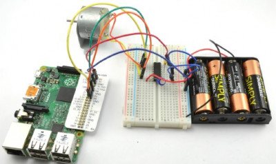
In this experiment, we will be using the L293D microchip, placing it on a prototype board. The assembled experiment circuit includes the prototype board with the L293D microchip, Raspberry Pi, a direct current motor, and a power source, as shown in the figure below:
-
image.png (162.38 KiB)
Schematic diagram of the experiment to control the speed and direction of rotation of an electric motor. using a Raspberry Pi assembly Viewed 26297 times
Components
For this experiment with Arduino and Raspberry Pi, you will need the following components:
IC1 - L293D H-Bridge Microchip
C1 - 100nF Capacitor
C2 - 16V 100µF Capacitor
M1 - Small DC Motor with a 6V power supply
Battery compartment for 4 AA batteries (6V)
400-point solderless prototype board
Male-to-Male Jumper Wires
Male-to-Female Jumper Wires (only for Raspberry Pi)
Experiment Circuit
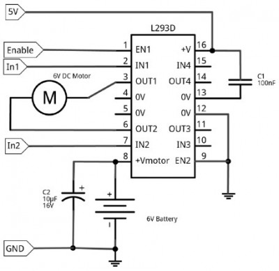
The circuit for this experiment is shown in the figure below. Raspberry Pi or Arduino provides a control voltage of 5V to the logic pin 16 of the L293D microchip. Power for the motor is supplied from a 6-volt battery pack to its pin 8.
Practically, only one of the H-bridges of the microchip is used here, so its pin EN2 is connected to ground to deactivate the unused part.
The pins EN1, IN1, and IN2 are connected to the digital output pins of Raspberry Pi or Arduino.
-
image.png (82.16 KiB)
L293D H-bridge wiring diagram Viewed 26297 times
CAPACITORS
As previously mentioned, using capacitors in the experiment is not necessary if we are only experimenting with this circuit for a few hours, as we are not primarily concerned with the reliability that capacitors could provide.
The capacitor positions shown in the diagram are quite typical for an H-bridge integrated circuit. Capacitor C1 is called a decoupling capacitor. It should be placed as close as possible to the microchip, between the logic signal and ground. The capacitance of capacitor C1 should not exceed 100nF (which is very small), but it helps eliminate various electrical noise that could potentially harm the logic of the microchip.
Capacitor C2 serves as an energy reservoir, which can provide power for some time, but this energy is specifically used to power the motor and is not consumed by the switching logic. The capacitance of this capacitor is usually much higher than that of C1, typically 100µF or more.
Prototype Board Layout
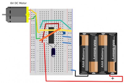
Before connecting the H-bridge to Arduino or Raspberry Pi, you can experiment with the circuit in standalone mode: check both the motor and the switching logic by powering them from the same 6-volt battery pack. This option is perfect if you want to test the microchip's operation without connecting it to Arduino or Raspberry Pi. However, when it comes to using the H-bridge with Arduino or Raspberry Pi, it's better to separate the power supply. The motor should receive power from the battery pack, while the logic of the microchip should be powered by Arduino or Raspberry Pi.
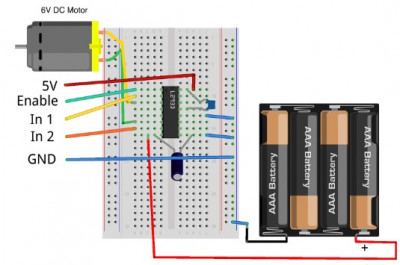
The figure below demonstrates the layout of the prototype board for autonomous testing. For working with Arduino or Raspberry Pi, you will hardly need to modify this layout; you will just need to rearrange some jumpers.
-
image.png (129.33 KiB)
Layout of breadboard for offline H-bridge testing Viewed 26297 times
When placing components on the prototype board, pay special attention to the microchip. It must be positioned correctly: a small cut on one side should be directed towards the upper part of the prototype board in row 10. To the left and above this cut, you should find pin 1.
Now you can connect the battery. Initially, the motor should not rotate.
CLOCKWISE AND COUNTERCLOCKWISE
When I mention that my motor is rotating clockwise or counterclockwise, your motor may actually rotate in the opposite direction. If your motor rotates counterclockwise when I say it should rotate clockwise, it's not a problem because it will rotate clockwise when I say "counterclockwise."
If you want your motor's rotation to match the description, you can swap the connecting wires.
Sometimes it can be difficult to determine in which direction the motor is rotating because it's just a bare metal shaft. You can simply touch it; if you gently grip the shaft with your thumb and index finger, you will understand the direction of rotation. You can also cut a short strip of colored adhesive tape and attach it to the spindle to serve as a makeshift flag.
Standalone Experiment
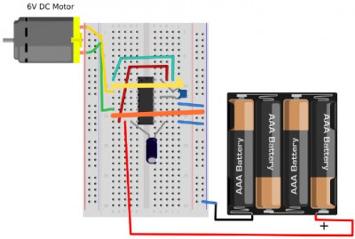
Regardless of the direction in which the motor should rotate - clockwise or counterclockwise, the Enable contact must be connected to +V. To make the motor rotate, for example, clockwise, connect the free end of the jumper that is already connected to IN1 to +V, and connect IN2 to the row labeled GND located on the right side of the prototype board.
-
image.png (119.43 KiB)
Starting the engine clockwise Viewed 26297 times
Now, we are going to reverse the motor's direction. You can leave the connection to Enable untouched, but you need to change the connections to IN1 and IN2 so that IN1 is now connected to GND, and IN2 is connected to +V, as shown in the diagram.
Please note: in the diagrams, IN1 and IN2 jumpers are depicted as thicker for easier differentiation from other jumpers.
Now that we have confirmed that the H-bridge is working as expected, we can connect our circuit to Arduino.
-
image.png (118.6 KiB)
Starting the engine counterclockwise Viewed 26297 times
Arduino Connection
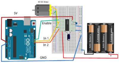
The diagram below shows how to connect the prototype board to Arduino Uno using jumpers. Contact number
11 on Arduino, used as Enable, supports PWM, and we will use the Enable contact of the L293D microchip to control the motor's speed. IN1 and IN2 can be connected to any digital contacts on Arduino; contacts
10 and
9 were chosen simply because they are located near contact
11, and when all the wires are neatly laid out, it looks cleaner.
Arduino supplies a 5V voltage to the logic part of the L293D, but it's essential to note that we are not powering the motor from Arduino; the motor's power is still coming from the batteries.
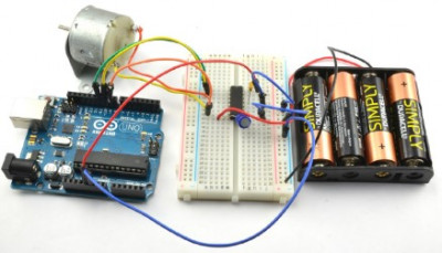
The prototype board, connected to Arduino with "male-to-male" jumpers, is shown in the diagram and is ready for operation.
-
image.png (132.37 KiB)
Connecting breadboard with H-bridge chip to Arduino Viewed 26297 times
-
image.png (165.59 KiB)
Схема управления двигателем с помощью Arduino в сборе Viewed 26297 times
Arduino Program
In the Arduino program we used in the section "Experiment: Controlling the Speed of a Direct Current Motor" (based on PWM), we used the serial monitor interface, which allowed us to send commands to the motor to adjust its speed. In this experiment, that program has been expanded; it now sends commands to control not only the speed but also the direction of rotation.
Here is the Arduino sketch for this experiment:
Code: Select all
const int enablePin = 11;  // (1)
const int in1Pin = 10;
const int in2Pin = 9;

void setup() {                 // (2)
  pinMode(enablePin, OUTPUT);
  pinMode(in1Pin, OUTPUT);
  pinMode(in2Pin, OUTPUT);
  Serial.begin(9600);
  Serial.println("Enter s (stop) or f or r followed by Duty Cycle (0 to 255). E.g. f120");
}

void loop() {                         // (3)
  if (Serial.available()) {
    char direction = Serial.read();   // (4)
    if (direction == 's') {           // (5)
      stop();                         // (6)
      return;
    }
    int pwm = Serial.parseInt();      // (7)
    if (direction == 'f') {           // (8)
      forward(pwm);
    }
    else if (direction == 'r') {
      reverse(pwm);
    }
  }
}

void forward(int pwm)          // (9)
{
  digitalWrite(in1Pin, HIGH);
  digitalWrite(in2Pin, LOW);
  analogWrite(enablePin, pwm);
  Serial.print("Forward ");
  Serial.println(pwm);
}

void reverse(int pwm)          // (10)
{
  digitalWrite(in1Pin, LOW);
  digitalWrite(in2Pin, HIGH);
  analogWrite(enablePin, pwm);
  Serial.print("Reverse ");
  Serial.println(pwm);
}

void stop()                    // (11)
{
  digitalWrite(in1Pin, LOW);
  digitalWrite(in2Pin, LOW);
  analogWrite(enablePin, 0);
  Serial.println("Stop");
}
This sketch, although relatively long, is well-structured with functions that make it easy to modify and reuse in your own projects. Let's go through the sketch's key points based on the comments:
1. The sketch begins by defining constants for the three control pins.
2. The
setup() function sets these pins as outputs, initializes the serial communication at 9600 baud, and sends a message to the serial monitor, explaining the format of commands used to control the motor.
3. The
loop() function continuously checks if there is any data available from the serial monitor.
4. If data is available, the first character is read as the direction (s for stop, f for forward, r for reverse).
5. If the direction is 's', the
stop() function is called, and the return statement ensures that no further code in
loop() is executed.
6. The 's' command doesn't require a
pwm parameter, so we don't attempt to read it from the message.
7. If the direction is 'f' or 'r' (not 's'), the
parseInt() function is used to extract the
pwm parameter from the remaining message.
8. Then, one of the functions,
forward() or
reverse(), is called depending on the
direction.
9. The
forward() function sets
in1Pin to
HIGH and
in2Pin to
LOW to specify the motor's rotation direction. It uses
analogWrite() to control the motor speed using
enablePin and the
pwm parameter. A confirmation message is sent to the serial monitor.
10. The
reverse() function is similar to
forward(), except
in1Pin is set to
LOW and
in2Pin is set to
HIGH, causing the motor to rotate in the opposite direction.
11. The
stop() function sets all control pins to
LOW and sets the motor's speed to 0 using
analogWrite(). A "Stop" message is sent to the serial monitor.
Loading and Running the Program
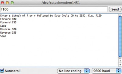
To perform the experiment with Arduino, connect your Arduino using a USB cable and upload the sketch. Open the serial port monitor, enter a command like
f100 in the top part of the window, and press the
Send button - the motor should start rotating very slowly in one direction.
-
image.png (67.28 KiB)
Motor control with serial commands Viewed 26297 times
Next, try entering the command
f255 - the motor will start rotating at full speed. The 's' command will stop the motor, the 'r100' command will slowly start it in the opposite direction, and the 'r255' command will accelerate the motor in the reverse direction to full speed.
HANDLE THE MOTOR WITH CAUTION
Imagine what would happen if a car were moving at full speed and then suddenly went into reverse. In the case of small motors with no massive components attached, this usually doesn't cause problems. However, when working with Arduino or Raspberry Pi powered from the same source as the motor, you may find that Raspberry Pi abruptly shuts down, and Arduino resets. This occurs because when changing directions suddenly, there is a very high current draw, causing a sharp drop in electrical power.
For large motors, a sudden change in speed or direction of a massive component with significant inertia can lead to serious issues. Not only can the increased currents potentially damage the H-bridge, but the motor's bearings can also experience mechanical stress.
This should be considered when developing control software for relatively large motors. To handle the motor gently, it's better to stop it before changing direction (create a delay during which it truly comes to a halt) and then start it again in the opposite direction. If you're using auxiliary functions like
forward and
reverse from the section "Experiment: Controlling Motor Direction and Speed," your code might look something like this in Arduino:
Code: Select all
forward(255);
delay(200);
reverse(255);