As there are two pairs of coils in a stepper motor, to control it, you'll need to reverse the current direction in each such pair, which means you'll need two H-bridges. It seems like the job for the L293D microchip.
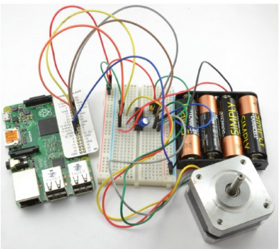
That's correct - in this experiment, both for Arduino and Raspberry Pi, the control of a bipolar stepper motor is achieved using the L293D microchip, which is installed on the prototype board.
-
image.png (239.48 KiB)
Bipolar stepper motor control circuit assembly (Raspberry Pi variant) Viewed 31250 times
Although the stepper motor used in the experiment has a nominal voltage of 12 V, it will work with a 6 V battery pack as well. The motor's torque will decrease, but it will still rotate effectively.
DEFINITION OF STEPPER MOTOR PINOUT
Every new stepper motor should have a technical datasheet as well as a label on its housing, indicating the purpose of each of its four pins. The key thing to know here is which pins form a pair connected to the same coil.
To figure this out, there's a simple trick. Take any two wires and hold them between your thumb and index finger while turning the motor's shaft. If you feel resistance to rotation, then these two wires form a pair.
Components
For this experiment, you will need the following components to work with Arduino and Raspberry Pi:
IC1 - L293D H-Bridge microchip
C1 - 100nF capacitor
C2 - 16V 100µF capacitor
M1 - Bipolar stepper motor 12V
4 AA battery compartment (6V)
400-point solderless prototype board
Jumper wires
Construction
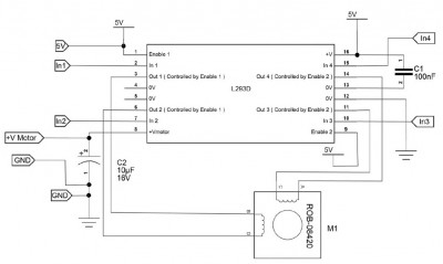
The schematic diagram of this experiment is shown below. In this case, PWM is not used, so both Enable inputs of the L293D microchip are connected to a 5V power source to keep both H-bridges permanently enabled. The stepper motor is controlled by four channels: In1, In2, In3, and In4, to which control signals from Arduino or Raspberry Pi will be applied.
Experimenting with Arduino
In this version of the Arduino experiment, we will use the serial monitor window to send commands to the Arduino that control the motor. There are three types of commands, each consisting of a single letter followed by a number. For example:
f100 - sets the motor to move 100 steps forward;
r100 - sets the motor to move 100 steps in reverse;
p10 - sets the delay time between step pulses to 10 milliseconds.
-
image.png (46.22 KiB)
Circuit diagram for controlling a bipolar stepper motor Viewed 31250 times
-
image.png (213.42 KiB)
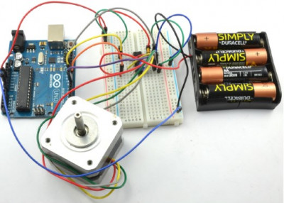
Stepper motor control circuit from Arduino assembly Viewed 31250 times
Connecting Arduino
When connecting Arduino to the L293D microchip, the following pins are used.

-
image.png (21.17 KiB)
Contacts for connecting Arduino to L293D chip Viewed 31250 times
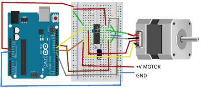
The layout of the prototype board for the Arduino version is shown in the figure below. Ensure that the microchip is correctly installed (the notch on the chip's housing should be facing upwards), and that the 100µF capacitor C2's positive terminal is connected to pin 8 of the L293D. To make it easier for you to orient, remember that the positive lead of an electrolytic capacitor is usually longer than the negative one. The negative terminal of the capacitor can also be marked on its body with a "-" symbol or a diamond.
-
image.png (106.54 KiB)
Layout of breadboard for controlling bipolar stepper motor with Arduino Viewed 31250 times
Arduino Programs
For this experiment, there are two program variants. The first one is more complex and involves setting up the L293D microchip's pins to control the stepper motor coils according to the description provided earlier in the "Bipolar Stepper Motors" section. This is a useful exercise for gaining a precise understanding of how a stepper motor works.
The second variant uses a sketch that calls the Arduino
Stepper library, which handles all the work. Therefore, the second variant is much shorter.
Complex Program Variant
The first Arduino sketch is as follows:
Code: Select all
const int in1Pin = 10;   // (1)
const int in2Pin = 9;
const int in3Pin = 11;
const int in4Pin = 8;

int period = 20;      // (2)

void setup() {        // (3)
  pinMode(in1Pin, OUTPUT);
  pinMode(in2Pin, OUTPUT);
  pinMode(in3Pin, OUTPUT);
  pinMode(in4Pin, OUTPUT);
  Serial.begin(9600);
  Serial.println("Command letter followed by number");
  Serial.println("p20 - set the inter-step period to 20ms (control speed)");
  Serial.println("f100 - forward 100 steps");
  Serial.println("r100 - reverse 100 steps");
}

void loop() {      // (4)
  if (Serial.available()) {
    char command = Serial.read();
    int param = Serial.parseInt();
    if (command == 'p') {        // (5)
      period = param;
    }
    else if (command == 'f') {   // (6)
      stepForward(param, period);
    }
    else if (command == 'r') {
      stepReverse(param, period);
    }
  }
  setCoils(0, 0, 0, 0); // power down
}

void stepForward(int steps, int period) {     // (7)
  for (int i = 0; i < steps; i++) {
    singleStepForward(period);
  }
}

void singleStepForward(int period) {       // (8)
  setCoils(1, 0, 0, 1);
  delay(period);
  setCoils(1, 0, 1, 0);
  delay(period);
  setCoils(0, 1, 1, 0);
  delay(period);
  setCoils(0, 1, 0, 1);
  delay(period);
}

void stepReverse(int steps, int period) {
  for (int i = 0; i < steps; i++) {200
    singleStepReverse(period);
  }
}

void singleStepReverse(int period) {          // (9)
  setCoils(0, 1, 0, 1);
  delay(period);
  setCoils(0, 1, 1, 0);
  delay(period);
  setCoils(1, 0, 1, 0);
  delay(period);
  setCoils(1, 0, 0, 1);
  delay(period);
}

void setCoils(int in1, int in2, int in3, int in4) {    // (10)
  digitalWrite(in1Pin, in1);
  digitalWrite(in2Pin, in2);
  digitalWrite(in3Pin, in3);
  digitalWrite(in4Pin, in4);
}
Let's clarify some points of the sketch step by step, using the comments made in the code:
1. The program begins by defining the pins that will be used to control the motor. You can, of course, change the pins according to how they are connected on the prototype board.
2. The variable
period sets the delay between activating the coils at each step during motor rotation. Initially, the delay is set to 20 ms. You can adjust this delay through the serial port monitor window to speed up or slow down the motor.
3. The
setup() function configures the control pins as outputs, initiates the serial communication channel with the serial port monitor window, and then prints a message containing the command formats that can be used.
4. In the main
loop() program loop, it waits for commands through the serial channel and processes these commands when received. If a command is received (as indicated by
Serial.available in the
loop() loop), it first reads the command letter and then the parameter following the letter.
Next, there are a series of expressions that define specific actions based on the command.
5. If a letter is specified, the variable "roy" takes the value equal to the command parameter.
6. If the "f" or "r" command is specified, it calls the
stepForward or
stepReverse functions with the number of steps and delay time between pulses as parameters.
7. The
stepForward and
stepReverse functions are very similar. They call the
singleStepForward or
singleStepReverse functions as many times as the specified steps.
8. Next, we move on to the
singleStepForward function, which contains the polarity patterns of the four-phase coil switching for moving one step. You can see the polarity patterns as parameters for
setCoils.
9. The
singleStepReverse function works the same way as
singleStepForward, but in the reverse sequence. Compare these steps with the data in the last table.
10. Finally, the function sets the state of the control pins according to the pattern provided as parameters.
Lightweight Program Variant
The Arduino IDE includes the
Stepper library, which works well and can significantly reduce the size of the sketch.
Code: Select all
#include <Stepper.h>    // (1)

const int in1Pin = 10;
const int in2Pin = 9;
const int in3Pin = 8;
const int in4Pin = 11;

Stepper motor(200, in1Pin, in2Pin, in3Pin, in4Pin);     // (2)

void setup() {       // (3)
  pinMode(in1Pin, OUTPUT);
  pinMode(in2Pin, OUTPUT);
  pinMode(in3Pin, OUTPUT);
  pinMode(in4Pin, OUTPUT);
  while (!Serial);
  Serial.begin(9600);
  Serial.println("Command letter followed by number");
  Serial.println("p20 - set the motor speed to 20");
  Serial.println("f100 - forward 100 steps");
  Serial.println("r100 - reverse 100 steps");
  motor.setSpeed(20);       // (4)
}

void loop() {        // (5)
    if (Serial.available()) {
    char command = Serial.read();
    int param = Serial.parseInt();
    if (command == 'p') {
      motor.setSpeed(param);
    }
    else if (command == 'f') {
      motor.step(param);
    }
    else if (command == 'r') {
      motor.step(-param);
    }
  }
}
Let's clarify some aspects of the sketch step by step, using the comments provided in the code:
1. In the first line of the sketch, the
Stepper library is imported, which is already included in the Arduino IDE, so you don't need to install it separately.
2. To use the library, you need to define the type of stepper motor in the
motor variable. The first parameter is the number of steps the motor takes in one revolution. For the Adafruit stepper motor used in this project, the value is set to
200 steps. In reality, this means 200 coil phase switches per revolution, which corresponds to 50 physical steps per revolution. The other four parameters are the pins used for the coils.
3. The setup function
setup() is almost the same as in the complex version of the sketch. However, the message differs slightly because in this case, the command sets the motor's rotation speed in RPM (revolutions per minute), which was previously adjusted by changing the delay between pulses. Either way, you can adjust the motor's speed using both methods.
4. By default, the rotation speed of the motor in the
setup() function is set using the
motor.setSpeed function, which is initially set to 20 RPM.
5. The main program loop
loop() is also very similar to the complex version of the sketch. However, in this case, the number of steps and the direction of rotation are specified as positive when moving forward and negative when moving backward.
The number of "quarter steps" specified in the
f and
r commands here represents the number of coil phase switches. To make the Adafruit stepper motor used here complete one full revolution, you need to enter the number 200.
Uploading and Running the Program
You can try both programs for stepper motors in all modes, but we will assume that the last sketch is loaded into Arduino. Open the serial port monitor, and you will see the message:
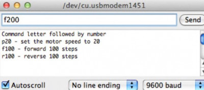
-
image.png (81.34 KiB)
Stepper motor control from the port monitor Viewed 31250 times
Enter the command
f200 and press the
Send button - the motor shaft should make one full revolution. If it doesn't rotate and instead vibrates or makes noise, one of the coils is likely connected incorrectly. Swap the jumpers going from the stepper motor to pins 3 and 6 of the L293D chip and try the command again.
Execute the
r200 command, after which the motor shaft should make one revolution in the opposite direction.
Next, you can experiment with the speed using the command and the subsequent speed value in RPM - for example,
p5 followed by
f200. The motor shaft will rotate again, but very slowly. You can increase the rotation speed by setting a higher value, for example,
p100. However, you'll find that somewhere around 130 RPM, there's a speed limit above which some steps will be lost, and the motor shaft won't be able to complete a full revolution.