In this project, we will add thermostat control to the project from the section "Project: Beverage Cooler" so that beverages can be cooled more accurately to the desired temperature (as shown in the diagram below). In the future, the project will be further developed by adding a display showing the set and actual temperatures.
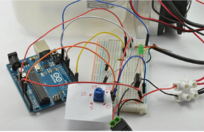 Equipment
This project is based on the project from the section "Project: Beverage Cooler," but with the addition of an Arduino board and a DS18B20 temperature sensor to the operational cycle. Therefore, if you have not yet worked on that project, please follow the instructions for its implementation provided in the section.
Components
In this project, the following components will be needed to work with Arduino:
R1 - 4.7 Ohm Resistor;
R2 - 1 kOhm Resistor;
R3 - 270 Ohm Resistor;
R4 - 10 kOhm Trimmer Resistor;
Sealed temperature sensor DS18B20;
Q1 - MOSFET transistor FQP30N06L;
LED1 - Green LED;
Thermoelectric cooling device with Peltier elements and two fans with a current consumption of no more than 4A;
Adapter with a round socket and screw clamps;
Power supply (12V 5A);
Bi-directional terminal block;
Large juice container;
The sealed temperature sensor DS18B20 contains the same microchip as used in the experiments from the section "Experiment: How good is a thermostat based on on/off switching?" and from the section "Experiment: Thermostatic PID controller," except that it comes in a convenient waterproof capsule with long wires that can be connected directly to the prototype board.
If a more powerful Peltier element is needed than the one listed, use a more powerful power supply to ensure that its maximum allowable current exceeds the current consumed by the element. Provide at least a half-ampere excess for the fans and another half-ampere just in case.
Project scheme
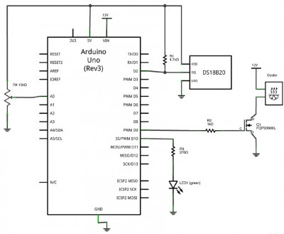
The schematic diagram of this project is shown in the image below. In the left part of the diagram, a trimmer resistor R4, also known as a potentiometer, is shown. The movable contact of the potentiometer is connected to pin A0, representing an analog input of the Arduino. The position of the potentiometer knob on pin A0 sets the voltage, which is measured by the Arduino and then used to set the desired cooler temperature.
Potentiometers
The component called a potentiometer should be familiar to you from volume controls of a radio receiver or amplifier. It has a knob that rotates almost a full turn.
The area around R4 in the image above shows how the potentiometer is used as an input device to Arduino: the top contact of the potentiometer is connected to the 5V line, and the bottom contact is connected to ground, while the voltage on the middle contact of the potentiometer will vary from 0 to 5V depending on the knob position.
The right part of the diagram in the image below is very similar to the experiment schematic in the section "Experiment: How good is a thermostat based on on/off switching?", except that a powerful MOSFET transistor FQP30N06L is used instead of the low-power transistor MPSA14. This transistor is capable of switching a current of 4A or more to the cooler, and its heating allows it to operate without a heatsink.
 Project assambly
Assuming you have already implemented the project from the section "Project: Beverage Cooler," to implement this project, you only need to perform the following additional steps.
Step 1: Adding the Temperature Sensor
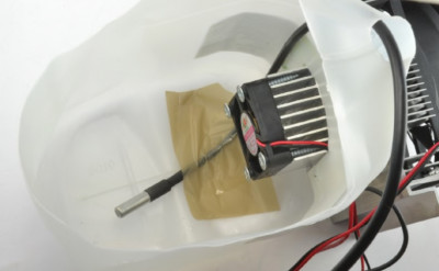
The physical construction of the cooler remains exactly the same as in the project from the section "Project: Beverage Cooler," but now you will add a temperature sensor, which should be placed at the bottom of the container - under the glasses or bottles being cooled on top of it (as shown in the diagram below). In this case, I simply attached the sensor to the bottom of the container with adhesive tape, but it is better to securely attach it in place.
 Step 2: Assembling the Circuit on a Breadboard
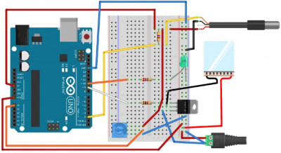
The diagram below shows the assembled circuit on a breadboard used for the project, along with the connections of various project components.
Place the components on the breadboard, ensuring the correct connection of the MOSFET transistor and LED. The temperature sensor has four wires in its cable. The wires with red and black insulation are connected respectively to the common power line (VCC) and ground (GND), and the wire with yellow insulation is the digital output of the sensor. The fourth wire does not need to be connected anywhere.
I attached a small piece of paper to the potentiometer knob, creating a primitive scale with markings to display the set cooler temperature.
 Step 3: Connecting the Cooler
The cooler has three pairs of wires: two for the fans and one for the Peltier element itself. To simplify the connection of the cooler, a bi-directional terminal block is used, allowing the cooler to be connected to the breadboard with just two wires (as shown in the diagram below).
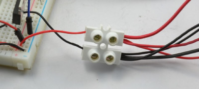 Step 4: Connecting the Power Supply
The adapter with a round socket and screw clamps can be connected to the breadboard using "male-to-male" jumper wires. While this option may be acceptable when using high-quality jumper wires with a relatively large cross-section, many jumper wires contain thin conductors that can heat up significantly from the current passing through them, especially when dealing with several amperes. This in itself does not pose a problem as long as these wires do not get too hot, instead of just being warm. However, this means that not all of the 12V will reach the Peltier element, and it will take longer for the cooler to enter its working mode.
To connect the breadboard to the power adapter, you can use a single-core insulated wire with a large cross-section instead of simple jumper wires. The same applies to the connecting wires leading to the cooler.
Arduino program
Using a PID controller for a beverage cooler may be considered excessive. However, in this case, the question boils down to the program, so there are no additional costs expected for using a "fancy" algorithm to maintain beverages in a chilled state.
The program for this project is largely similar to the one used in the experiments from the section "Experiment: How good is a thermostat based on on/off switching?" and from the section "Experiment: Thermostatic PID controller," including all the code for interfacing with the temperature sensor DS18B20. Therefore, to understand this code, you should refer back to the descriptions of the mentioned experiments.
Code: Select all
#include <OneWire.h>
#include <DallasTemperature.h>
#include <PID_v1.h>

const double minTemp = 0.0;  //1
const double maxTemp = 20.0;
const float tempOKMargin = 0.5;

double kp = 1500;     //2
double ki = 50.0;
double kd = 0.0;

const int tempPin = 2;
const int coolPin = 9;
const int ledPin = 10;   //3
const int potPin = A0;
const long period = 1000; // >750

OneWire oneWire(tempPin);
DallasTemperature sensors(&oneWire);

double setTemp = 0.0;
double measuredTemp = 0.0;
double outputPower = 0.0;
long lastSampleTime = 0;

PID myPID(&measuredTemp, &outputPower, &setTemp, kp, ki, kd, REVERSE); //4

void setup() {
  pinMode(coolPin, OUTPUT);
  pinMode(ledPin, OUTPUT);
  Serial.begin(9600);
  sensors.begin();
  myPID.SetSampleTime(1000); // (4)
  myPID.SetMode(AUTOMATIC);
}

void loop() { //5
  long now = millis();
  if (now > lastSampleTime + period) {
      checkTemperature();
      lastSampleTime = now;
  }
  setTemp = readSetTempFromPot(); //6
}

void checkTemperature() {      //7
  measuredTemp = readTemp();
  Serial.print(measuredTemp);
  Serial.print(", ");
  Serial.print(setTemp);
  Serial.print(", ");
  Serial.println(outputPower);
  myPID.Compute();
  analogWrite(coolPin, outputPower);
  float error = setTemp - measuredTemp;//8
  if (abs(error) < tempOKMargin) {
    digitalWrite(ledPin, HIGH);
  }
  else {
    digitalWrite(ledPin, LOW);
  }
}

double readSetTempFromPot() {   //9
  int raw = analogRead(potPin);
  double temp = map(raw, 0, 1023, minTemp, maxTemp);
  return temp;
}

double readTemp() {
  sensors.requestTemperatures();
  return sensors.getTempCByIndex(0);
}
Let's clarify some points in the program step by step, using the line annotations provided in the comments:
1. The temperature range set by the potentiometer is determined by two constants: minTemp and maxTemp. The variable tempOKMargin defines the value above or below the set temperature that the actual temperature can have before the green LED turns off.
2. A relatively high value is set for kp to ensure that the cooler turns on and off more precisely. This is mainly done to eliminate the dull sound of the fan motors when they are powered at low output power levels. Instead, the fans can be powered separately to run continuously, and only regulate the power to the Peltier element.
3. Additional contacts are defined for the LED and potentiometer.
4. The PID controller is initialized in
REVERSE mode instead of
DIRECT(as before) because adding output power will lower, not raise, the temperature.
5. In the main loop, the passage of a one-second interval is checked, and the
checkTemperaturefunction is called as needed to turn the cooler on and off.
6. Each cycle (which should occur several times per second) calls the
readsetTempFromPot function to set the
setTempvariable based on the potentiometer position.
7. The
checkTemperature function measures the temperature, reads the data obtained, and then updates the PID controller. This function also writes the read data to the serial monitor window, allowing you to adjust the cooler or track its operation. Arduino does not need to be connected via the USB port since it receives power through its
Vin pin, but if it is connected via the USB port, the output data can be viewed on the serial monitor window.
8. The rest of this function includes turning on the LED if the measured temperature is within an acceptable deviation from the set temperature, determined by the
tempOKMargin constant. The
abs function (absolute value) removes the minus sign from a number.
9. The code for converting the potentiometer position into a value between
minTemp and
maxTemp. The raw analog read (values ranging from 0 to 1023) is stored in the variable raw. Then, the map function is called to convert the read value into the desired temperature range (see the section below for more details).
MAP FUNCTION USED IN ARDUINO
When controlling devices with Arduino or Raspberry Pi, there is often a need to convert a number from one range of values to another range of values.
For example, on an Arduino analog input with a range of values from 0 to 1023, if you need to map this range to a temperature range, such as from 0 to 20, you can simply divide the number by 51.15 (i.e., 1023/20). Then, 1023 will be converted to 1023/51.15 = 20.
The task becomes more complex when both ranges do not start at zero. This is where the built-in map function in Arduino can be useful. As shown below, it takes five parameters to convert a number from the range of 0 to 1023 to a range of 20 to 40
map(value, 0, 1023, 20, 40);
Here, the first parameter is the value to be converted, the second and third parameters define the range of the existing value, and the fourth and fifth define the range in which to obtain the corresponding value (in this case, the range from 20 to 40).
In the Python language, there is no built-in range function, but it can be easily created and then used in your program. It should look something like this:
Code: Select all
def map(value, from_low, from_high, to_low, to_high):
    from_range = from_high - from_low
    to_range = to_high - to_low
    scale_factor = from / to_range
    return to_low + (value / scale_factor)
Then you can call this function in Python with the same parameters as its Arduino counterpart. For example:
map(510, 0, 1023, 20, 40)
As a result, the function will return the value 30, which is the midpoint value for the range from 20 to 40, just as the value 510 is roughly in the middle of the range from 0 to 1023.