Motors, pumps and actuators
Posted: 25 Jul 2024, 00:48
Motors, pumps and actuators
In a previous experiment, we've already worked with a DC motor. The fundamental principles we'll learn while dealing with DC motors are applicable to many other mechanisms you might want to control with Arduino or Raspberry Pi. Electro-motors, in particular, enable various useful output devices, including pumps and linear actuators, which we'll become acquainted with.
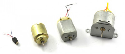
In the image below, you can see a selection of various sizes and shapes of DC motors.

As we learned from the "Experiment: Controlling a DC Motor," you can't directly control a DC motor with the contacts of Arduino or Raspberry Pi because it requires a relatively high current. Therefore, we used a transistor to enable us to turn the motor on and off. Now, our goal is to learn how to control its rotation speed.
HOW DO DC MOTORS WORK?
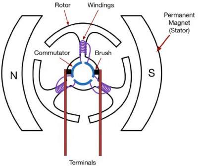
Typically, a DC motor consists of three main parts, as shown in the illustration: the external (stationary) part of the motor is the stationary magnet (stator), and on the shaft inside the stator is the moving part of the motor, composed of the rotor and the commutator.
The rotor carries wire coils (windings). In the illustration, you can see three such coils wound around three shaped segments of the rotor, connected to the commutator. The purpose of the commutator is to sequentially excite the magnetic field in the coils as the rotor rotates, ensuring that the next coil is always attracted to the stator's permanent magnets, thus causing the rotor to spin.
The commutator is a segmented ring (three segments are shown in the illustration), and brushes are used to connect the power contacts to individual segments of the commutator as it rotates together with the rotor.

The model of a DC motor with three sets of windings described here is quite typical for such small DC motors, as shown in the image at the beginning. A valuable property of DC motors is that changing the polarity of the voltage on the contacts makes the motor rotate in the opposite direction.
In a previous experiment, we've already worked with a DC motor. The fundamental principles we'll learn while dealing with DC motors are applicable to many other mechanisms you might want to control with Arduino or Raspberry Pi. Electro-motors, in particular, enable various useful output devices, including pumps and linear actuators, which we'll become acquainted with.
In the image below, you can see a selection of various sizes and shapes of DC motors.
As we learned from the "Experiment: Controlling a DC Motor," you can't directly control a DC motor with the contacts of Arduino or Raspberry Pi because it requires a relatively high current. Therefore, we used a transistor to enable us to turn the motor on and off. Now, our goal is to learn how to control its rotation speed.
HOW DO DC MOTORS WORK?
Typically, a DC motor consists of three main parts, as shown in the illustration: the external (stationary) part of the motor is the stationary magnet (stator), and on the shaft inside the stator is the moving part of the motor, composed of the rotor and the commutator.
The rotor carries wire coils (windings). In the illustration, you can see three such coils wound around three shaped segments of the rotor, connected to the commutator. The purpose of the commutator is to sequentially excite the magnetic field in the coils as the rotor rotates, ensuring that the next coil is always attracted to the stator's permanent magnets, thus causing the rotor to spin.
The commutator is a segmented ring (three segments are shown in the illustration), and brushes are used to connect the power contacts to individual segments of the commutator as it rotates together with the rotor.
The model of a DC motor with three sets of windings described here is quite typical for such small DC motors, as shown in the image at the beginning. A valuable property of DC motors is that changing the polarity of the voltage on the contacts makes the motor rotate in the opposite direction.